3.5.4.2.2. Placement 3.5.4.2.2.5. Créer un point d'attache pour les pièces rapportées |  |
| Précédent | Suivant |
Dans le cas où votre géométrie comporte un point d'attache pour ...
... qui doit être transféré vers Revit, veuillez suivre la procédure décrite ci-dessous et publier le point de connexion eCATALOG 3Dfindit comme l'un des points mentionnés ici.
![[Remarque]](https://webapi.partcommunity.com/service/help/latest/pages/fr/installation_ecatalogsolutions/doc/images/note.png)
Ouvrez le fichier 3db et placez le point d'attache nécessaire. Le nom est libre.
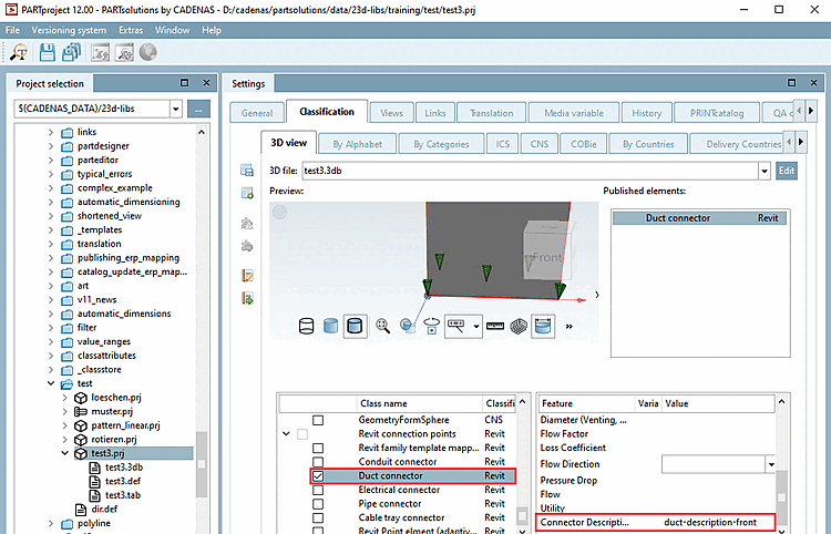
Sélectionnez l'onglet Classification, puis la sous-page Vue 3D [3D view].
Ouvrez la boîte de dialogue Sélectionner un point d'attache [Choose connection point] via le menu contextuel de la vue 3D.
Sélectionnez le point souhaité et confirmez en cliquant sur .
Sous Classification Revit, activez la classe Duct connector.
-> Une entrée apparaît sous Éléments publiés [Published elements].
Saisissez un texte de description sous Connector Description.
![[Astuce]](https://webapi.partcommunity.com/service/help/latest/pages/fr/installation_ecatalogsolutions/doc/images/tip.png)
Les points d'attache peuvent être créés partout dans eCATALOG3Dfindit. Les points d'attache fonctionnels (adaptés à Revit) doivent être créés au centre d'une surface plane (centre de gravité), par exemple le centre d'un cercle ou le point d'intersection de toutes les tangentes d'angle (voir https://en.wikipedia.org/wiki/Centroid).
Il est recommandé de créer une extrusion à l'endroit où le point d'attache doit être placé (>1,4 mm de diamètre / longueur d'extrusion).
Si aucune surface plane n'est disponible dans le 3db, l'interface CADENAS Revit tentera de créer un "corps factice" (2x2x2 millimètres) à l'endroit où le point d'attache doit être créé. Cela ne devrait pas être la méthode préférée lors de la création d'un modèle, car le résultat final dans Revit ne sera pas identique à 100 % au modèle eCAT.