3.5.4.2.5. Classification - Exemple 3.5.4.2.5.2. Classer le point d'attache de placement |  |
| Précédent | Suivant |
Pour qu'un composant puisse être placé automatiquement, un point d'assemblage prévu à cet effet doit être classé en conséquence.
La porte de garage utilisée ici à titre d'exemple est un sous-ensemble. Le point d'attache correspondant doit donc être disponible au niveau du sous-ensemble. Ensuite, la classification peut être effectuée directement au niveau du sous-ensemble.
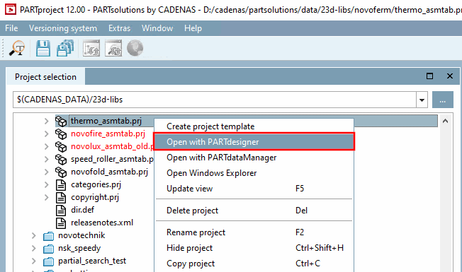
Sélectionner le projet de tableau d'assemblage (*asmtab.prj) et cliquer sur la commande Ouvrir avec PARTdesigner [Open with PARTdesigner] du menu contextuel.
-> La configuration de l'assemblage s'ouvre.
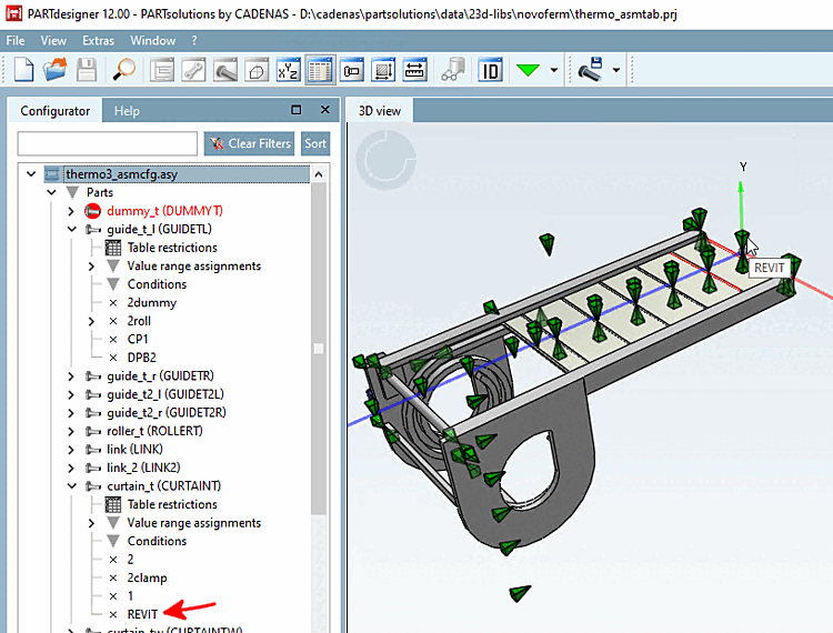
Sur le plan principal, ouvrez le menu contextuel et cliquez sur Ajouter un point d'attache de partage [Add shared connection point].
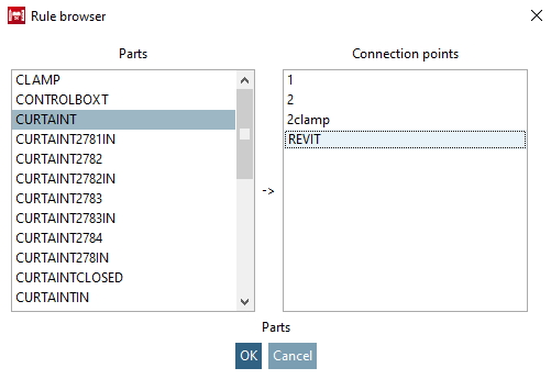
Dans le navigateur de règles [Rule browser], déterminez la partie et le point d'attache.
-> Le point d'attache de partage a été ajouté.
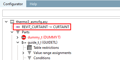
Point d'attache de placement dans la configuration (ici dans l'exemple "REVIT_CURTAINT -> CURTAINT")
Sélectionnez le fichier gabarit correspondant (*.asmtpl.prj) et ouvrez l'onglet Classification, puis la sous-page Vue 3D [3D view].
(Aucun contenu 3D n'est affiché pour les assemblages).
-> Le point d'attache de partage est affiché dans la boîte de dialogue du même nom.
Sélectionnez le point et confirmez avec .
-> L'interface standard habituelle pour déterminer les éléments publiés s'affiche désormais.
Activez la classe Placement Coordinatessytem dans la classification CNS.
-> La classe s'affiche sous Éléments publiés [Published elements].
![Ajouter un point d'attache de partage [Add shared connection point]](https://webapi.partcommunity.com/service/help/latest/pages/fr/partwarehouse/doc/resources/img/img_9716b8206ee2420793b141a4677b77b0.png)
![Sélectionner le point d'attache [Choose connection point] (pour l'assemblage)](https://webapi.partcommunity.com/service/help/latest/pages/fr/partwarehouse/doc/resources/img/img_44d31066d986464ab1e3d6403e86aa7f.png)