![Modifier [Modify] -> Transformer [Transform] (groupé)](https://webapi.partcommunity.com/service/help/latest/pages/fr/partsolutions_user/doc/resources/img/img_8f75c1fa6ad94770b2086392f496f1f2.png)
![[Remarque]](https://webapi.partcommunity.com/service/help/latest/pages/fr/partsolutions_user/doc/images/note.png) | Remarque |
|---|---|
Les boutons de la barre d'outils Transformation [Transform] ne peuvent être sélectionnés que lorsqu'un élément de dessin est sélectionné . | |
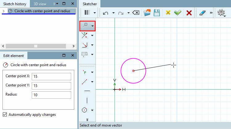
 Reporter la sélection [Move selection]
Déplacer un élément de dessin à l'aide d'un vecteur
Sélectionnez l'élément de dessin que vous souhaitez déplacer.
Choisir le point de départ du vecteur de déplacement [Choose start of move vector] / Choisir le point final du vecteur de déplacement [Select end of move vector]: Vous pouvez choisir le point de départ et le point final à n'importe quel endroit.
-> L'élément est ensuite immédiatement déplacé de la longueur et de la direction du vecteur.
Dans la fenêtre Editer élément [Edit element], adaptez éventuellement les coordonnées vectorielles X-offset [x offset] et Y-offset [y offset]. Vous pouvez ainsi positionner l'élément avec précision.
 sélection de copie et
reporter [Copy and move selection]
sélection de copie et
reporter [Copy and move selection]
Copier et déplacer un élément de dessin à l'aide d'un vecteur (p. ex. pour plusieurs perçages identiques)
Cliquez sur l’icône Bouton Copier
sélection et
. [Copy and move selection]
Choisir le point de départ du vecteur de déplacement [Choose start of move vector] / Choisir le point final du vecteur de déplacement [Select end of move vector]: Vous pouvez choisir le point de départ et le point final à n'importe quel endroit.
-> L'élément est immédiatement copié et déplacé de la longueur et de la direction du vecteur.
Adaptez éventuellement les coordonnées vectorielles X-offset [x offset], Y-offset [y offset] dans la fenêtre Editer élément [Edit element]. Vous pouvez ainsi positionner l'élément avec précision.
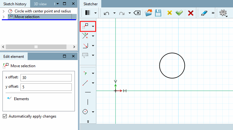
Adaptez éventuellement aussi le nombre [Number] de copies. Par défaut, 1 copie est d'abord créée. L'ill. ci-dessous montre 2 copies.
La figure montre l'original et 2 copies, chacune décalée avec un décalage X [x offset] de 30 et un décalage Y [y offset] de 5.
Comme alternative à la fonction décrite, Vous
également sélection
tout en [Move selection]
maintenant la touche Ctrl enfoncée en même temps.
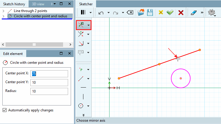
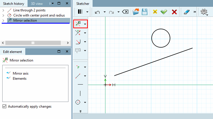
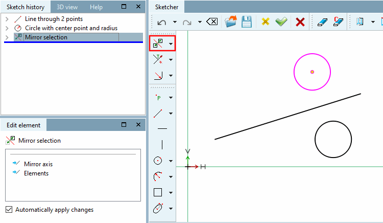
 Sélection de mise en miroir [Mirror selection] (et d’original
supprimer)
Sélection de mise en miroir [Mirror selection] (et d’original
supprimer)
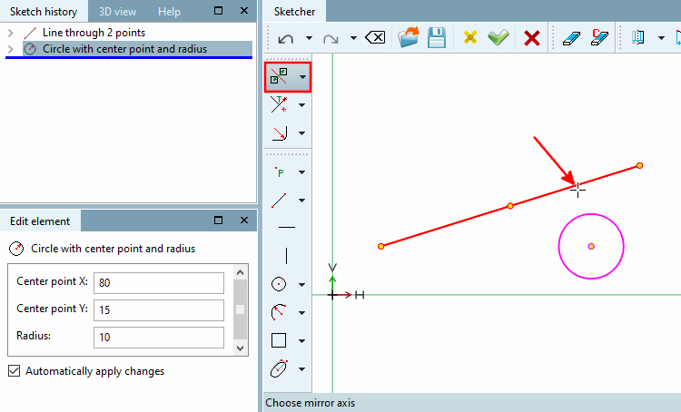
 Sélection de copie et de symétrie [Copy and mirror selection] (Sélection
miroir et garder l’original)
Sélection de copie et de symétrie [Copy and mirror selection] (Sélection
miroir et garder l’original)
Copier l'élément de dessin et le mettre en miroir sur un le mettre en miroir.
En alternative à la fonction décrite, Vous pouvez aussi imiter le bouton
Sélection [Mirror selection]
tout en maintenant la touche Ctrl enfoncée en même temps
utiliser.
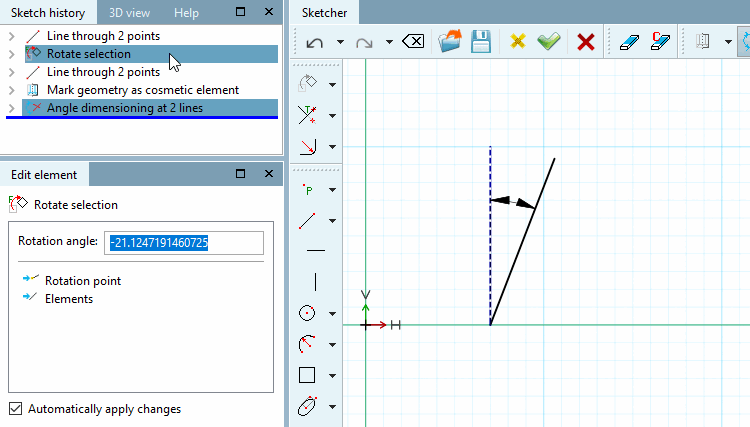
 Rotation de la sélection [Rotate selection] (Rotation et Original)
supprimer)
Rotation de la sélection [Rotate selection] (Rotation et Original)
supprimer)
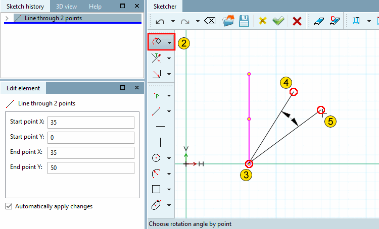
Faire pivoter l'élément de dessin sur un point [Point] avec un angle donné
Cliquez sur le bouton
sélection
Rotation [Rotate selection].
Indiquer l'angle de référence par un point [Choose reference angle by point]: Déterminez l'angle de rotation à l'aide de deux points de référence quelconques qui couvrent l'angle.
Cliquez sur un point qui détermine la première ligne de référence de l'angle.
Indiquer l'angle de rotation par rapport au point [Choose rotation angle by point]:
Cliquez sur un point qui détermine la deuxième ligne de référence de l'angle.
-> Dès que vous avez fixé le deuxième point, l'élément pivote immédiatement de l'angle formé par les deux lignes.
Corrigez éventuellement l' angle de rotation [Angle of rotation] dans la fenêtre Editer l'élément [Edit element]. (Si la deuxième ligne était à droite de la première, une valeur négative est affichée, sinon une valeur positive).
Faire pivoter les points d'attache [Rotate connection points]: Voir le point suivant ci-dessous
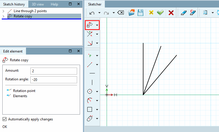
 Copier et faire pivoter la sélection [Copy and rotate selection] (Rotation
et garder l’original)
Copier et faire pivoter la sélection [Copy and rotate selection] (Rotation
et garder l’original)
Copier l'élément de dessin et le faire pivoter sur un point [Point] avec un angle donné
Cliquez sur le bouton
sélection de copie et
Rotation [Copy and rotate selection].
Indiquer l'angle de référence par un point [Choose reference angle by point]: Déterminez l'angle de rotation à l'aide de deux points de référence quelconques qui couvrent l'angle.
Cliquez sur un point qui détermine la première ligne de référence de l'angle.
Indiquer l'angle de rotation par rapport au point [Choose rotation angle by point]:
Cliquez sur un point qui détermine la deuxième ligne de référence de l'angle.
-> Dès que vous avez fixé le deuxième point, l'élément pivote immédiatement de l'angle formé par les deux lignes.
Corrigez éventuellement l' angle de rotation [Rotation angle] dans la fenêtre Editer l'élément [Edit element] et indiquez le nombre de copies souhaitées sous Nombre [Amount].
L'angle de rotation a été adapté ici à "-20" et le nombre de copies à 2 (la valeur par défaut est 1).
Comme alternative à la fonction décrite, Vous pouvez également faire pivoter [Rotate selection] le bouton
Sélection
tout en maintenant la touche Ctrl enfoncée en même temps
utiliser.
Faire pivoter les points d'attache [Rotate connection points]:
Vous pouvez également faire pivoter les points d'attache.
Dans ce cas, la fonction correspondante est également affichée. Le point d'attache est alors également tourné avec l' angle de rotation [Rotation angle] indiqué.
Faire pivoter les points d'attache [Rotate connection points]: Dans le Sketcher en haut, l'option est désactivée, en bas, elle est activée.
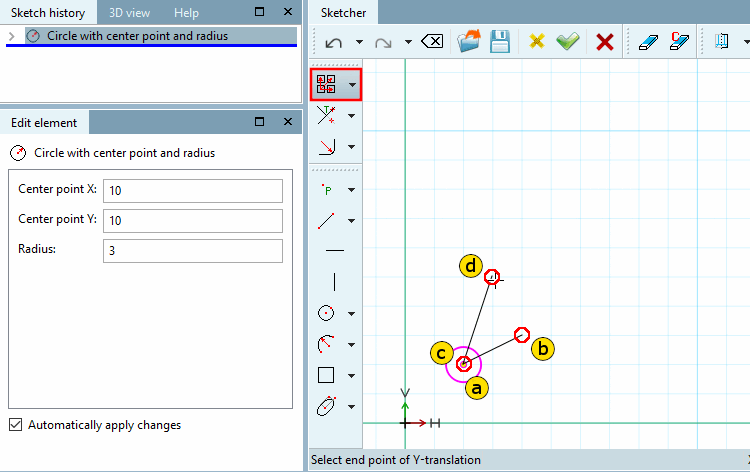
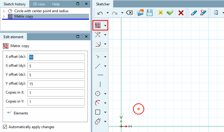
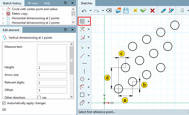
 Copie matricielle [Matrix copy]
Copier un élément de dessin en lignes et en colonnes
Cliquez sur les points de début et de fin du déplacement :
Choisir le point de départ du déplacement X [Choose start point of X-translation]
Sélectionner le point final du décalage X [Select end point of X-translation]
Choisir le point de départ du déplacement Y [Choose start point of Y-translation]
Sélectionner le point final du déplacement en Y [Select end point of Y-translation]
Dès que le dernier des quatre points est déterminé, la fenêtre d'ancrage Editer l'élément [Edit element] s'ouvre. Dans un premier temps, aucune copie n'est encore visible, mais seulement l'élément d'origine.
Adaptez éventuellement les paramètres.
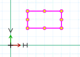
 Copie de variante [Variant copy]
Copierun élément de dessin pour Copier
Sélectionnez tous les éléments du dessin (multi-sélection en maintenant la touche Ctrl enfoncée, ou bien dessiner un cadre en maintenant la touche Shift)
Cliquez avec le bouton secondaire de la souris dans l’espace libre pour désactiver les fonctionnalités précédentes et Cliquez ensuite sur le bouton
variante copier [Variant copy].
Sélectionnez le point de référence et le point d'insertion pour l'élément sélectionné (le groupe sélectionné). (L'accrochage indique si un point est saisi).
-> La fenêtre Editer l'élément [Edit element] s'ouvre.
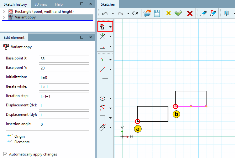
Modifiez les paramètres selon vos besoins :
Point de base [Base point] X: Coordonnée X Point d'insertion de la première copie
Point de base [Base point] Y: Coordonnée Y Point d'insertion de la première copie
Initialisation [Initializing]: valeur de départ de la variable "I
Poursuite de la commutation [Iteration step]: valeur de poursuite de la commutation (en règle générale, aucune modification n'est nécessaire ; avec 2, un élément serait toujours sauté)
Déplacement (dx) [Displacement (dx)]: déplacement de l'élément en direction de l'axe X par étape d'itération
Déplacement (dy) [Displacement (dy)]: déplacement de l'élément en direction de l'axe Y par étape d'itération
Angle d'insertion [Insertion angle]: rotation de l'élément sélectionné (du groupe sélectionné) d'un angle par étape d'itération.
-> Les copies de l'élément sont placées en fonction des paramètres de base.
Dans l'exemple ci-dessous, cinq copies de l'élément sélectionné sont créées. Les copies sont décalées de 30 dans la direction de l'axe x et de 0 dans la direction de l'axe y à chaque étape d'itération et sont tournées de 45° à chaque étape.
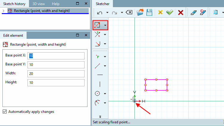
 éléments d’échelle [Scale elements]
Sélectionner le point fixe de mise à l'échelle [Set scaling fixed point...]... : Le sens de l'expansion dépend du point fixe choisi.
Si un point d'angle est utilisé comme point fixe, les éléments sont alors déplacés dans les autres points.
Si le point fixe est le centre, les éléments sont agrandis de la même manière dans toutes les directions.
Si le point fixe se trouve en dehors des éléments sélectionnés, la distance des éléments par rapport au point fixe est également mise à l'échelle.
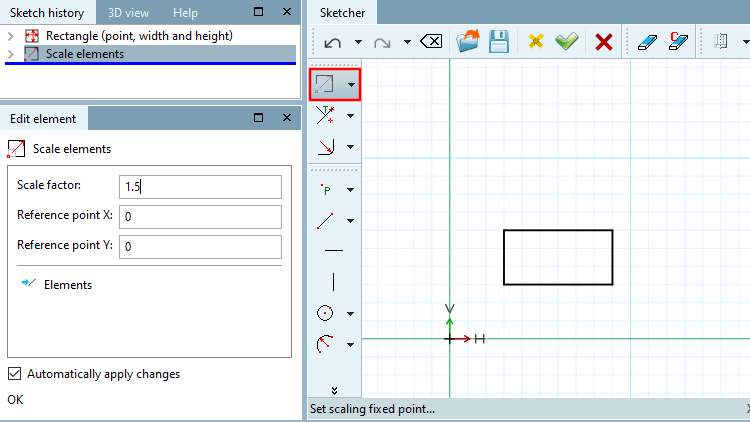
-> La fenêtre d'accueil Editer l'élément [Edit element] s'ouvre.
Saisissez le facteur d'échelle [Scale factor] dans le champ de saisie.
Les valeurs supérieures à 1 augmentent l'élément d'origine, les valeurs inférieures à 1 diminuent l'élément d'origine.
Exemple : mise à l'échelle d'un rectangle
 décalage des contours [Contour offset]
L'outil Décalage du contour [Contour offset] crée un double du contour avec un facteur d'échelle.
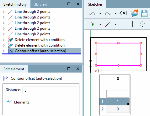
 Décalage des contours (sélection automatique) [Contour offset (auto-selection)]
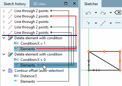
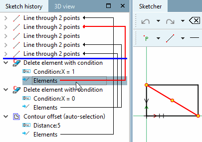
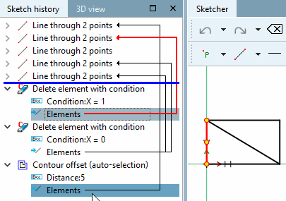
L'outil Contouroffset (auto-sélection) [Contour offset (auto-selection)] crée un double du contour complété automatiquement avec un facteur d'échelle (cf. Contouroffset [Contour offset] ). La sélection d'un seul élément est suffisante.
En supposant qu'un sketch est modifié par des conditions qui accèdent à des variables de table, Konturoffset [Contour offset] ne fonctionne pas, car toutes les sélections doivent être présentes dès le début.
Les deux illustrations suivantes montrent comment dessiner une fois un triangle et une fois un quadrilatère.
Sélectionnez un élément défini comme Point de départ pour
décalage de contour
(Sélection automatique) [Contour offset (auto-selection)] est à utiliser. L’élément doit être
se présentent dans les deux variantes.
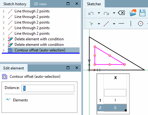
Dans la fenêtre d'ancrage Editer l'élément [Edit element], saisissez le décalage souhaité sous Distance.
-> L' offset de contour [Contour offset] est effectué correctement dans tous les cas.
![La figure montre l'original et 2 copies, chacune décalée avec un décalage X [x offset] de 30 et un décalage Y [y offset] de 5.](https://webapi.partcommunity.com/service/help/latest/pages/fr/partsolutions_user/doc/resources/img/img_f83e084c4b2c460eacd03fd6f2a8c531.png)
![Faire pivoter les points d'attache [Rotate connection points]: Dans le Sketcher en haut, l'option est désactivée, en bas, elle est activée.](https://webapi.partcommunity.com/service/help/latest/pages/fr/partsolutions_user/doc/resources/img/img_1f44fc3a6fc048818acfd06013e62cdb.png)


![Résultat de l' offset de contour [Contour offset]](https://webapi.partcommunity.com/service/help/latest/pages/fr/partsolutions_user/doc/resources/img/img_53672998d19b4ff4bd03e48295ec4b77.png)