3.5.4.2.2. Posizionamento 3.5.4.2.2.5. Creare un punto di attacco per i componenti aggiuntivi |  |
| Indietro | Avanti |
Nel caso in cui la vostra geometria abbia un punto di connessione per ...
... che devono essere trasferiti a Revit, procedere come descritto di seguito e pubblicare il punto di connessione eCATALOG 3Dfindit come uno dei punti qui menzionati.
![[Nota]](https://webapi.partcommunity.com/service/help/latest/pages/it/partsolutions_user/doc/images/note.png)
Aprire il file 3db e impostare il punto di connessione richiesto. Il nome può essere scelto liberamente.
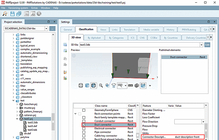
Selezionare la pagina della scheda Classificazione [Classification] e quindi la sottopagina Vista 3D [3D view].
Aprire la finestra di dialogo Seleziona punto di connessione [Choose connection point] tramite il menu contestuale della vista 3D.
Attivare la classe del connettore Duct nella classificazione di Revit.
-> Sotto Elementi pubblicati [Published elements] compare una voce.
Inserire un testo di descrizione in Descrizione del connettore.
![[Suggerimento]](https://webapi.partcommunity.com/service/help/latest/pages/it/partsolutions_user/doc/images/tip.png)
I punti di connessione possono essere creati in qualsiasi punto di eCATALOG3Dfindit. I punti di connessione funzionali (adatti a Revit) devono essere creati nel centro di una superficie piana (baricentro), ad esempio il centro di un cerchio o l'intersezione di tutte le tangenti angolari (vedere https://en.wikipedia.org/wiki/Centroid).
Si consiglia di creare un'estrusione nella posizione in cui deve essere collocato il punto di connessione (diametro >1,4 mm / lunghezza dell'estrusione).
Se in 3db non è disponibile alcuna superficie piana, l'interfaccia di CADENAS Revit cercherà di creare un "corpo fittizio" (2x2x2 millimetri) nella posizione in cui deve essere creato il punto di connessione. Questo non dovrebbe essere il metodo preferito per la creazione di un modello, poiché il risultato finale in Revit non sarà identico al 100% al modello eCAT.