3.5.4.2.2. Posizionamento 3.5.4.2.2.4. Classificare il punto di connessione del posizionamento |  |
| Indietro | Avanti |
Selezionare il componente da classificare.
In Impostazioni [Settings], passare alla pagina della scheda Classificazione [Classification] e quindi alla sottopagina Vista 3D [3D view].
Richiamare l'omonima finestra di dialogo utilizzando il comando del menu contestuale Seleziona punto di connessione [Choose connection point].
Selezionare il punto di connessione di posizionamento e confermare con .
-> Si apre l'area di dialogo per gli elementi pubblicati [Published elements].
Attivare la classe Sistema di coordinate di posizionamento nella classificazione CNS.
-> La classe viene visualizzata sotto gli elementi pubblicati [Published elements].
![Selezionare il punto di connessione [Choose connection point] (per la singola parte)](https://webapi.partcommunity.com/service/help/latest/pages/it/partsolutions_user/doc/resources/img/img_95860de45ac24cd0ab7da46b66b9446d.png)
Se si utilizza un assieme, è necessario specificare il punto di connessione da utilizzare (cioè quale singolo pezzo con quale punto di connessione).
![[Nota]](https://webapi.partcommunity.com/service/help/latest/pages/it/partsolutions_user/doc/images/note.png)
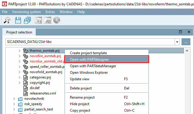
Selezionare il progetto della tavola di montaggio (*asmtab.prj) e fare clic sul comando del menu contestuale Apri con PARTdesigner [Open with PARTdesigner].
-> Si apre la configurazione di montaggio.
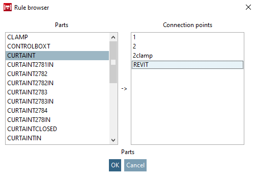
Aprire il menu contestuale del livello principale e fare clic su Aggiungi punto di collegamento alla condivisione [Add shared connection point].
Determinare la parte e il punto di connessione nel browser delle regole [Rule browser].
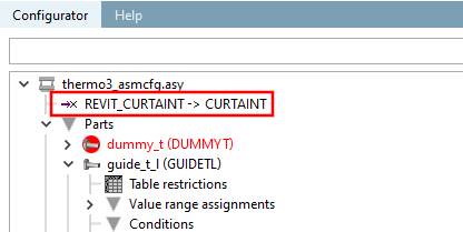
-> È stato aggiunto il punto di attacco per il rilascio.
Figura 3.124. Punto di collegamento della configurazione (nell'esempio "REVIT_CURTAINT -> CURTAINT")
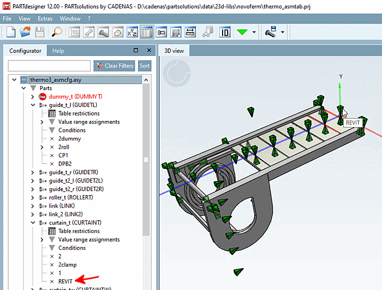
Selezionate il file modello corrispondente (*.asmtpl.prj) e aprite la pagina della scheda Classificazione [Classification] e poi la sottopagina Vista 3D [3D view].
(Per gli assiemi non viene visualizzato alcun contenuto 3D).
-> Il punto di attacco di rilascio viene visualizzato nell'omonima finestra di dialogo.
Selezionare la voce e confermare con .
-> Viene ora visualizzata la nota interfaccia standard per la determinazione degli elementi pubblicati.
Attivare la classe Sistema di coordinate di posizionamento nella classificazione CNS.
-> La classe viene visualizzata sotto gli elementi pubblicati [Published elements].
![Aggiungere un punto di attacco per il rilascio [Add shared connection point]](https://webapi.partcommunity.com/service/help/latest/pages/it/partsolutions_user/doc/resources/img/img_31440558dd624152bcacf08b5a4d786e.png)
![Selezionare il punto di connessione [Choose connection point] (per il montaggio)](https://webapi.partcommunity.com/service/help/latest/pages/it/partsolutions_user/doc/resources/img/img_a12cbcfb76fe472bb1ad5fa3bfe715a1.png)