7.6.2.11.2. Modifica/creazione di tubature (percorsi di tubature)
7.6.2.11.2.3.
Elementi
|  |
| Indietro | Avanti |
Il percorso del tubo può essere specificato nella sezione Elementi [Elements].
![Sezione "Elementi [Elements]](https://webapi.partcommunity.com/service/help/latest/pages/it/partwarehouse/doc/resources/img/img_eab2dcce08f34cc0a93fd16191e9dd7d.png)
Funzioni sotto elementi [Elements]:
Indice errori
 : Questa icona e l'etichetta associata
indicare se sono presenti errori e, in caso affermativo, in quali
Elemento.
: Questa icona e l'etichetta associata
indicare se sono presenti errori e, in caso affermativo, in quali
Elemento.
Elemento: singolo elemento del tratto di tubazione. Un percorso di tubature è composto da almeno uno e fino a un numero qualsiasi di elementi. (Teoricamente illimitato -> la RAM ne limita il numero). Seguiranno ulteriori informazioni su ciascun tipo di elemento.
Nuova operazione di seguito inserire. [Add new operation below.]
 (non visibile nella figura sopra)/ Elimina questa operazione. [Delete this operation.]

Tutte le operazioni togliere. [Remove all operations.]
 : Poiché un corso di tubi è costituito da almeno un tubo
deve esistere, rimane un elemento vuoto.
: Poiché un corso di tubi è costituito da almeno un tubo
deve esistere, rimane un elemento vuoto.
Aiuto
 : I disegni tecnici aiutano il singolo
Compila correttamente i campi.
: I disegni tecnici aiutano il singolo
Compila correttamente i campi.

Ogni campo di input di questo gruppo (le eccezioni sono segnalate) consente variabili tabellari e/o locali ed espressioni (solo espressioni comuni di PARTdesigner, vedere Sezione 10.1, “PARTdesigner-Espressioni ” ). Se si utilizzano variabili, il debug è limitato al valore corrente della variabile. Alcune costellazioni di valori di variabili potrebbero portare a una parte non valida, ma convalidare ogni possibile costellazione di variabili comporterebbe un immenso sforzo di calcolo.
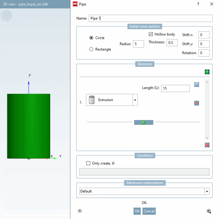
L' estrusione [Extrusion] (tubo diritto) è l'elemento più semplice. Viene estruso solo in base alla lunghezza data.
![Elemento "estrusione [Extrusion]](https://webapi.partcommunity.com/service/help/latest/pages/it/partwarehouse/doc/resources/img/img_744786acdabb4254afa46846dbf356bb.png)
![di aiuto per "Estrusione [Extrusion]"](https://webapi.partcommunity.com/service/help/latest/pages/it/partwarehouse/doc/resources/img/img_9f4c96546ca649bd85860cf5cabeac75.png)
![di aiuto per "Estrusione [Extrusion]"](https://webapi.partcommunity.com/service/help/latest/pages/it/partwarehouse/doc/resources/img/img_f8e4435d44a2435da6b307ab5c3de4e2.png)
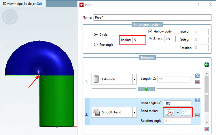
La flessione circolare [Smooth bend] crea un corpo di rotazione.
![Elemento "Curva rotonda [Smooth bend]](https://webapi.partcommunity.com/service/help/latest/pages/it/partwarehouse/doc/resources/img/img_04df011505694aa293f819361e09820b.png)
![Aiuto per "Piegatura rotondo [Smooth bend]"](https://webapi.partcommunity.com/service/help/latest/pages/it/partwarehouse/doc/resources/img/img_f6d01cdf8dd1430bb50f76446c7550d9.png)
Angolo di piegatura (A) [Bend angle (A)]: Immettere un angolo che descrive quanto il tubo deve essere piegato in questo elemento (sezione di un arco). Sono validi tutti i valori compresi tra 0° e 360°.
Raggio di curvatura [Bend radius]: inserire il raggio del cerchio che il tubo segue.
Commutazione per il punto di riferimento del raggio: fare clic sulla freccia per aprire una casella di riepilogo e passare da una modalità all'altra:
Angolo di rotazione [Rotation angle]: specificare l'angolo per l'orientamento del tratto di tubo. È valido qualsiasi angolo compreso tra 0° e 360° (360° equivale a 0°).
![Angolo di piegatura [Bend angle] 90°](https://webapi.partcommunity.com/service/help/latest/pages/it/partwarehouse/doc/resources/img/img_6617367ddb9e4491bf460560ff91b501.png)
![Angolo di piegatura [Bend angle] 180°](https://webapi.partcommunity.com/service/help/latest/pages/it/partwarehouse/doc/resources/img/img_c7cba87a393e44ec8a16123c1b2844cd.png)
![Raggio di curvatura [Bend radius] 15 con angolo di curvatura [Bend angle] di 180](https://webapi.partcommunity.com/service/help/latest/pages/it/partwarehouse/doc/resources/img/img_8bd8487639ae4c10af18446c434441ea.png)
![Raggio di curvatura [Bend radius] 6 con angolo di curvatura [Bend angle] di 180](https://webapi.partcommunity.com/service/help/latest/pages/it/partwarehouse/doc/resources/img/img_ba16bce15722470191c24209ebac8a76.png)


![Angolo di rotazione [Rotation angle] 180](https://webapi.partcommunity.com/service/help/latest/pages/it/partwarehouse/doc/resources/img/img_b1a5c6099cfb421b9998d92ed6efd370.png)
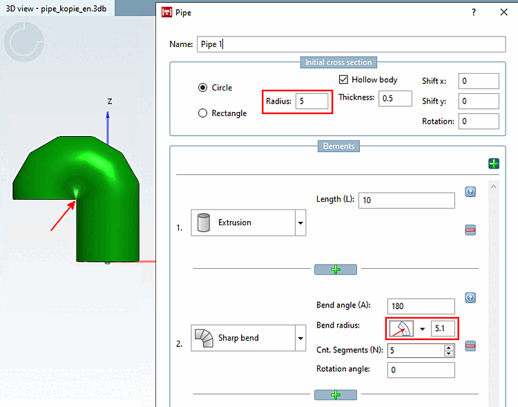
Gli elementi di curva quadrata [Sharp bend] e di curva circolare [Smooth bend] sono simili, tranne che per il fatto che la curva quadrata [Sharp bend] è composta da elementi tubolari diritti collegati con un certo angolo (di solito saldati nella pratica).
![Elemento "Curva angolare [Sharp bend]](https://webapi.partcommunity.com/service/help/latest/pages/it/partwarehouse/doc/resources/img/img_313a14f5fd3c412f8f452a7f3d990170.png)
![Guida per "Piega squadra [Sharp bend]"](https://webapi.partcommunity.com/service/help/latest/pages/it/partwarehouse/doc/resources/img/img_6a877f7333004926b1259b3ad20961fd.png)
Angolo di curvatura [Bend angle]: inserire un angolo che descrive la distanza del tubo da piegare in questo elemento (sezione di un arco). Sono validi tutti i valori compresi tra 0° e 360°.
Raggio di curvatura [Bend radius]: inserire il raggio del cerchio che il tubo segue.
![[Nota]](https://webapi.partcommunity.com/service/help/latest/pages/it/partwarehouse/doc/images/note.png)
Nota Il punto di ancoraggio del raggio deve essere esterno alla geometria.
A Modalità di piegatura
 Raggio centrale (Rc) [Center radius (Rc)]
un cerchio con raggio 5 necessita di un valore maggiore
come 5. Nel caso di rettangoli ruotati, è
più complicato, ma risoluzione dei problemi
rilascerà un suggerimento,
se il raggio è troppo piccolo.
Raggio centrale (Rc) [Center radius (Rc)]
un cerchio con raggio 5 necessita di un valore maggiore
come 5. Nel caso di rettangoli ruotati, è
più complicato, ma risoluzione dei problemi
rilascerà un suggerimento,
se il raggio è troppo piccolo.
Interruttore per il punto di riferimento del raggio: fare clic sull'icona per passare da una modalità all'altra:
Numero di segmenti [No. segments]: Il numero di segmenti di tubo utilizzati per approssimare un cerchio. Questo campo non ammette variabili o espressioni.
Angolo di rotazione [Rotation angle]: specificare l'angolo per l'orientamento del percorso del tubo.
I valori validi dipendono dal tipo di sezione trasversale. Per il tipo circolare [Circle], tutti i valori sono validi. Per il tipo rettangolare [Rectangle], i valori sono limitati a 0°, 90°, 180° e 270° per motivi di compatibilità verso il basso.
![Angolo di piegatura [Bend angle] 90°](https://webapi.partcommunity.com/service/help/latest/pages/it/partwarehouse/doc/resources/img/img_10092d574f06482ab10bc1658ea6a214.png)
![Angolo di piegatura [Bend angle] 180°](https://webapi.partcommunity.com/service/help/latest/pages/it/partwarehouse/doc/resources/img/img_394648d076c94e03a9e6da19c9b2a700.png)
![N. di segmenti (N) [Cnt. Segments (N)]: "0"](https://webapi.partcommunity.com/service/help/latest/pages/it/partwarehouse/doc/resources/img/img_9ffa483a30644951a4725c917ab28ca9.png)
![Numero di segmenti (N) [Cnt. Segments (N)]: "3".](https://webapi.partcommunity.com/service/help/latest/pages/it/partwarehouse/doc/resources/img/img_e4ef0b89994a45f8b44dd728d006f479.png)
L'elemento di modifica della sezione trasversale [Cross section change] consente di modificare la forma e/o l'orientamento della sezione trasversale. Le sezioni trasversali di ingresso e di uscita saranno quindi diverse. Questo vale per tutti i seguenti elementi.
![Elemento "Variazione della sezione trasversale [Cross section change]](https://webapi.partcommunity.com/service/help/latest/pages/it/partwarehouse/doc/resources/img/img_870225e8f1ee458199ffe9baf0ad0e27.png)
![Aiuto su "Cambiamento trasversale [Cross section change]"](https://webapi.partcommunity.com/service/help/latest/pages/it/partwarehouse/doc/resources/img/img_404a9dda832b485490aa974238a4074b.png)
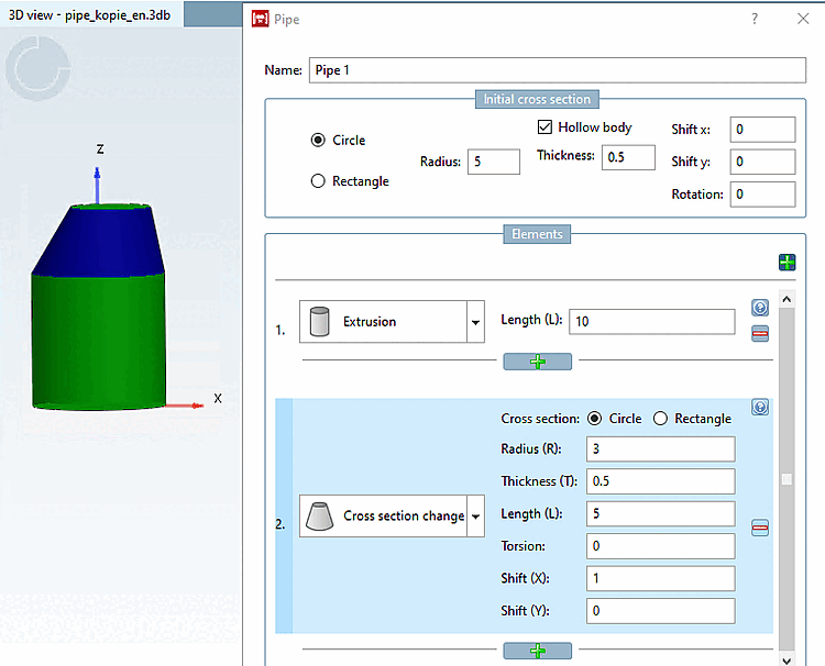
Sezione [Cross section]: selezionare il tipo di sezione (cerchio [Circle] / rettangolo [Rectangle] ).
Raggio (R) [Radius (R)]: (dimensione della sezione trasversale): Definisce la dimensione della nuova sezione trasversale.
Figura 7.175, “ Sezione iniziale [Initial cross section] -> cerchio [Circle] ”S pessore della parete (T) [Thickness (T)]: attivo solo se l'intero tubo è cavo (vedere ). In caso affermativo, è necessario inserire un valore.
Torsione [Torsion]: rotazione del piano della sezione trasversale intorno al suo centro. Il valore è limitato a un massimo di 180°. Tuttavia, valori elevati portano a solidi strani. Controllare il risultato nell'anteprima e, in caso di dubbio, dividere l'elemento in 2 elementi, ciascuno con metà della lunghezza e metà della torsione.
L'esempio seguente mostra le sweep con una sezione trasversale rettangolare.
Spostamento: (Spostamento X [Translation X] / Spostamento Y [Translation Y] ) Inserire i valori corrispondenti per determinare una sezione trasversale decentrata sull'elemento terminale.
![Torsione [Torsion] 0°](https://webapi.partcommunity.com/service/help/latest/pages/it/partwarehouse/doc/resources/img/img_9a1f7e84849f4a249197b81d155f1d83.png)
![Torsione a [Torsion] 45°](https://webapi.partcommunity.com/service/help/latest/pages/it/partwarehouse/doc/resources/img/img_41973a82d7504a2f8a6ca7540d0b7309.png)
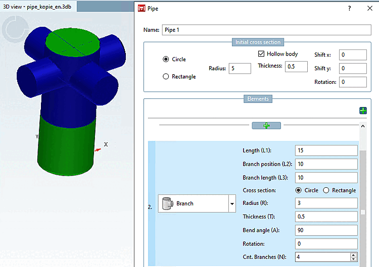
L'elemento di ramificazione [Branch] consente di aggiungere rami separati a un tubo. Determinare il numero e la forma degli elementi di ramificazione. In seguito, è possibile aggiungere nuovi tubi a ciascun ramo.
![Elemento "ramo [Branch]](https://webapi.partcommunity.com/service/help/latest/pages/it/partwarehouse/doc/resources/img/img_2444dee538784c2d8c58df4fe23c378a.png)
![di aiuto per "Diramazione [Branch]"](https://webapi.partcommunity.com/service/help/latest/pages/it/partwarehouse/doc/resources/img/img_7ea17d8b4a7f4c15b42e6de702b6240c.png)
Lunghezza (L1) [Length (L1)]: lunghezza del ramo principale.
Posizione dei rami (L2) [Branch position (L2)]: Posizione dei rami laterali.
Lunghezza dei rami (L3) [Branch length (L3)]: Lunghezza dei rami laterali.
Nota Il valore deve essere almeno la metà del diametro del ramo principale (sezione trasversale di ingresso). Il punto di partenza (invisibile) del ramo laterale è il centro del ramo principale. Se il valore è maggiore del raggio del ramo principale, si assicura che il ramo laterale sporga dal ramo principale.
Sezione trasversale [Cross section] (cerchio [Circle] / rettangolo [Rectangle] ): Selezionare il tipo di sezione trasversale dei rami laterali.
Determinare il raggio (R) [Radius (R)] e lo spessore della parete (T) [Thickness (T)] dei rami laterali. Il campo di immissione in Spessore parete (T) [Thickness (T)] è attivo solo se l'opzione Sezione cava [Hollow body] è attivata in Sezione iniziale [Initial cross section].
Angolo di curvatura (A) [Bend angle (A)]: Rappresenta l'angolo tra il ramo principale e i suoi rami laterali. Per impostazione predefinita, il valore è impostato su "90", che dà luogo a un ramo a forma di "T".
Rotazione [Rotation]: determina l'angolo per la direzione del primo ramo laterale (l'impostazione predefinita è 0° e corrisponde alla direzione dell'asse X).
Numero di rami (N) [Cnt. Branches (N)]: determina il numero di rami laterali. I rami laterali sono distribuiti equamente intorno al ramo principale. Questo campo non ammette variabili o espressioni.
Sezione 7.6.2.11.4, “Comandi del menu contestuale” Le informazioni su come elaborare ulteriormente il tubo nei punti di diramazione sono disponibili in -> Diramazioni.