
![[Nota]](https://webapi.partcommunity.com/service/help/latest/pages/it/partwarehouse/doc/images/note.png)
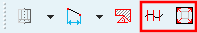
 Interruzione di polilinee [Split polyline]
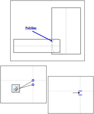
Le polilinee, come quelle create dall'intersezione di due cilindri, vengono scomposte da questa funzione in singoli segmenti "calcolabili" (archi, ellissi, ecc.).
La polilinea può quindi essere elaborata o tagliata come gruppo di singoli segmenti e trasferita a un sistema CAD con proprietà "riconoscibili".
Nell'esempio a destra (sezione molto ingrandita), la polilinea [Polyline] può essere catturata e tagliata, ad esempio spezzando un elemento tra 2 punti [Cut element between 2 elements].
 Disegno in scala [Scale drawing]
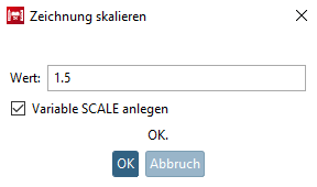
Fare clic sull'icona del disegno in scala [Scale drawing] per aprire l'omonima finestra di dialogo.
Inserire il fattore di scala [Scale factor] desiderato nel campo Valore [Value].
Attivare facoltativamente la variabile Crea scala [Create variable SCALE].
-> Il disegno viene scalato e si apre la finestra di aggancio Modifica elemento [Edit element].
È possibile regolare il fattore di scala [Scale factor] e il punto di riferimento [Reference point] X / Y nella finestra di aggancio Modifica elemento [Edit element].
Fattore di scala [Scale factor]: valori > 1 ingrandiscono l'elemento o gli elementi originali, valori < 1 riducono la dimensione
Punto di riferimento [Reference point] X / Punto di riferimento [Reference point] Y: per impostazione predefinita, il punto zero è il punto di riferimento; tuttavia, è possibile selezionare qualsiasi punto di riferimento.

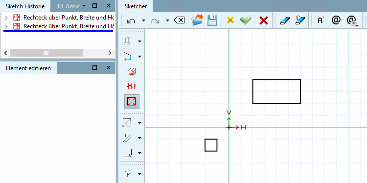
![Disegno scalato con fattore di scala [Scale factor] 1,5](https://webapi.partcommunity.com/service/help/latest/pages/it/partwarehouse/doc/resources/img/img_6cc127bd16024a4696f24f6f205fbd1c.png)