7.13.3.2.
Créer une configuration d'assemblage
7.13.3.2.2. Règles pour les points d'attache
|  |
| Précédent | Suivant |
Des règles sont maintenant définies pour garantir une structure correcte de l'assemblage.
Sur le
point d’attache (  ) de la partie factice (base_dummy), l’attache « [Connection part]
fluegel1 » avec son
Point
d’attache [Connection point] « milieu » au moyen d’un
Règle [Rule] ajoutée.
) de la partie factice (base_dummy), l’attache « [Connection part]
fluegel1 » avec son
Point
d’attache [Connection point] « milieu » au moyen d’un
Règle [Rule] ajoutée.
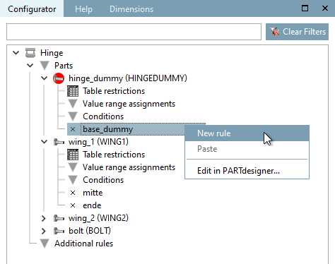
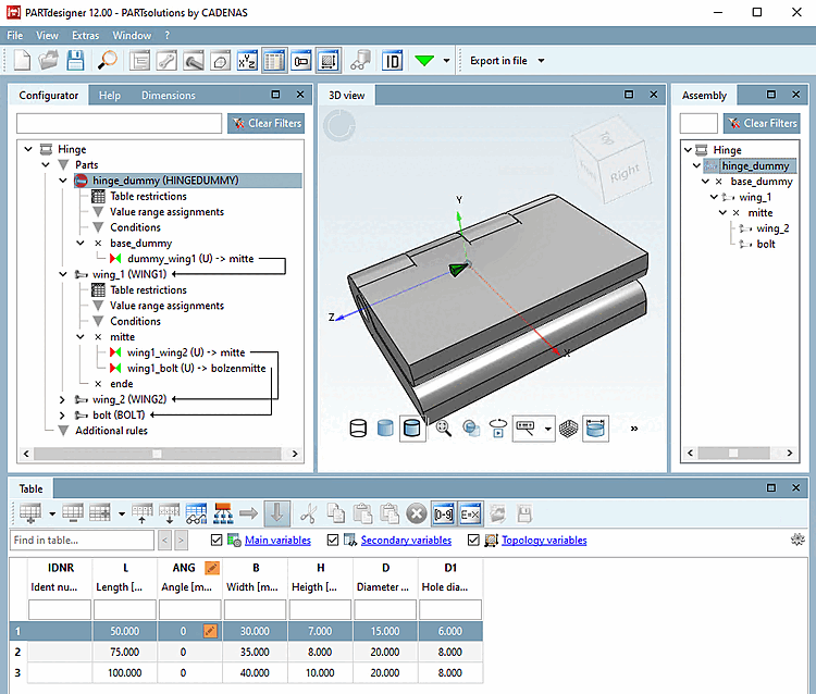
Sur "base_dummy", appelez la commande Nouvelle règle [New rule].
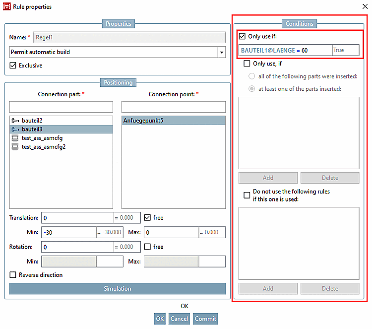
→ La boîte de dialogue Propriétés de la règle [Rule properties] s'ouvre.
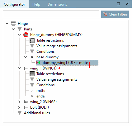
Sous pièce jointe [Connection part], sélectionnez "aile1" et sous point d'attache [Connection point] "milieu".
→ Le lien entre le point d'ajout "base_dummy" et "fluegel1" est représenté par une ligne fléchée rouge.
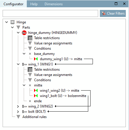
Reliez maintenant, à l'aide d'autres règles, fluegel1 avec fluegel2 et boulons ou alternativement fluegel2 avec boulons.
Après l'exécution de tous les liens, on obtient l'image suivante :
Construisez maintenant la configuration dans la fenêtre de docking Structure [Assembly] à l'aide de la liste de sélection et de la sélection des lignes du tableau en alternance.
Pour pouvoir commander la position angulaire de manière variable, procédez comme suit :
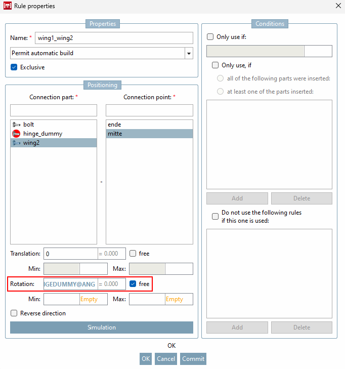
Sur fluegel1 , appelez le menu contextuel du point d’attache (
la boîte de dialogue Propriétés de la règle [Rule properties] .
Dans la zone Positionnement [Positioning], effectuez la saisie suivante dans le champ Rotation:
SCHARNIERDUMMY@ANG
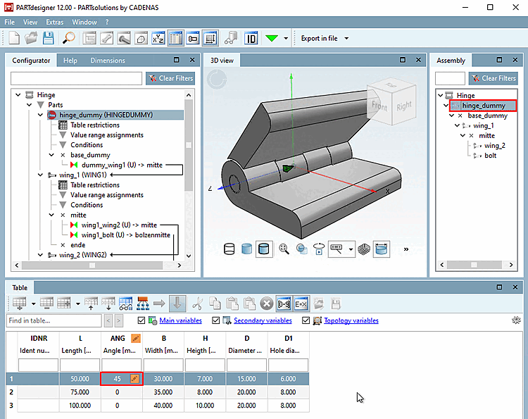
La variable de plage de valeurs "ANG" se trouve dans la partie fictive, qui n'est pas exportée, mais la table de la partie fictive est utilisée par le projet de table d'assemblage. La commande de la position angulaire s'effectue ainsi dans l'assemblage.
Vous pouvez maintenant régler l'angle d'ouverture de la charnière au moyen de la variable de domaine de valeurs "ANG".
Si vous avez la configuration de l’ensemble dans le Ouvrez PARTdataManager, voir Après avoir sélectionné le bouton Afficher la structure de l’assemblage [Show assembly structure], vous
 voir dans un graphique comment les pièces individuelles sont affichées via le
Les règles sont liées les unes aux autres.
voir dans un graphique comment les pièces individuelles sont affichées via le
Les règles sont liées les unes aux autres.
![Boîte de dialogue "Propriétés de la règle [Rule properties]](https://webapi.partcommunity.com/service/help/latest/pages/fr/partsolutions_user/doc/resources/img/img_76818e00d3514662ba0a2d5f84b736d4.png)
![Afficher la structure d'assemblage [Show assembly structure]](https://webapi.partcommunity.com/service/help/latest/pages/fr/partsolutions_user/doc/resources/img/img_f1761b83f1664072b691f5953e10dfcc.png)
![[Remarque]](https://webapi.partcommunity.com/service/help/latest/pages/fr/partsolutions_user/doc/images/note.png)