
- 7.16.1. Esempio: creare la quotatura
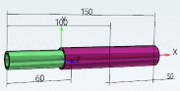
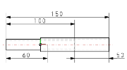
- 7.16.2. Dimensioni orizzontali, verticali e parallele
- 7.16.3. Dimensioni radiali
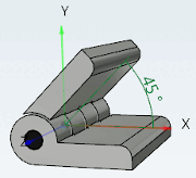
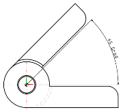
- 7.16.4. Dimensioni dell'angolo
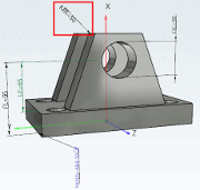
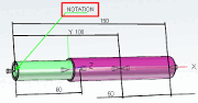
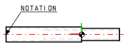
- 7.16.5. Notazione
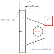
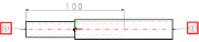
- 7.16.6. NOTAZIONE PARZIALE
- 7.16.7. Dettagli dei parametri opzionali
- 7.16.8. Parametri 3D
- 7.16.9. Uso delle variabili
- 7.16.10. Espressioni PARTdesigner
Creare dimensioni (notazioni) per la vista 3D [3D view] e la derivazione 2D [2D derivation]
In PARTdesigner, le dimensioni [Dimensionings] possono essere create parametricamente in una finestra di aggancio separata durante il processo di modellazione. Le singole dimensioni possono anche essere impostate come modificabili in modo che l'utente finale possa fare clic su di esse e selezionare varianti alternative dei componenti. (Vedere Sezione 7.16.7, “ Dettagli dei parametri opzionali ” -> Mappatura delle variabili [Variable mapping] ).
In 3Dfindit, queste dimensioni vengono generate automaticamente per la vista 3D [3D view] e la derivazione 2D [2D derivation] nella selezione della parte [Part selection]. Quando si esporta, la derivazione 2D [2D derivation] viene trasferita al sistema CAD.
| Dimensioni orizzontali, verticali e parallele | Dimensioni radiali | Dimensioni dell'angolo | Note / numeri di articolo per l'elenco delle parti |
|
|
|
|
|
|
|
|
|
|
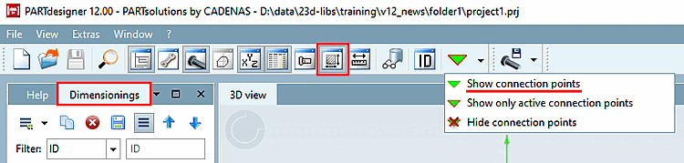
Se la finestra di ancoraggio Dimensioni (Dimensions [Dimensionings] ) non è visualizzata, richiamare
 tramite l'icona della barra degli strumenti.
Assicurarsi che i punti di connessione siano visualizzati nella vista 3D [3D view].
Se necessario, fare clic sul pulsante Mostra punti di connessione [Show connection points] nella barra degli strumenti standard.
Impostare prima i punti di quota richiesti (se non già presenti)
Poiché i punti di misura fanno riferimento a punti di quota/punti di attacco, questi devono essere già presenti nel componente o essere impostati in modo specifico.
I punti di connessione [Connection points] (visualizzati in verde nei singoli pezzi, in grigio negli assiemi) possono essere utilizzati allo stesso modo dei punti di quota puri (visualizzati in blu).
È essenziale notare su quale superficie/piano sono impostati i punti di quota!
Se i punti di quota non sono impostati correttamente, la quotatura nella vista 3D [3D view] con l'opzione di impostazione della proiezione prospettica [Perspective projection] sembra puntare ai punti sbagliati.
I punti di quota devono essere posizionati il più vicino possibile all'osservatore.
File per il salvataggio dei parametri di dimensionamento
È per la gestione delle dimensioni non è ancora disponibile, il file progetto, un file con lo stesso nome del progetto
*.dimcreato automaticamente e il Chiave CUSTOMDIMENSIONSV9 in File di progetto di configurazione dell'assembly (*asmcfg.prj), file di progetto del modello di assembly (*asmsbl.prj) o il file di progetto dell'articolo (*.prj) punta a questo*.dim.Se un file
customdimensions.txtè ancora esaurito versioni precedenti, continuerà ad essere utilizzato ed esistente Dati letti da lì.In entrambi i casi, non è necessario intervenire manualmente.
![Proiezione prospettica [Perspective projection] da](https://webapi.partcommunity.com/service/help/latest/pages/it/partwarehouse/doc/resources/img/img_c83cb7c98cc8415782095dec979d9f89.png)
![Proiezione prospettica [Perspective projection] su](https://webapi.partcommunity.com/service/help/latest/pages/it/partwarehouse/doc/resources/img/img_d2d67261d8c14a30b72a57e24cbb207f.png)
Non utilizzare le traduzioni per il dimensionamento automatico! [113] Utilizzare invece una variabile dell'intervallo di valori con un nome [Value range variable with naming] di testo neutro.
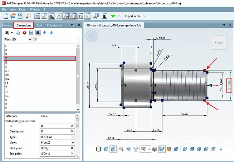
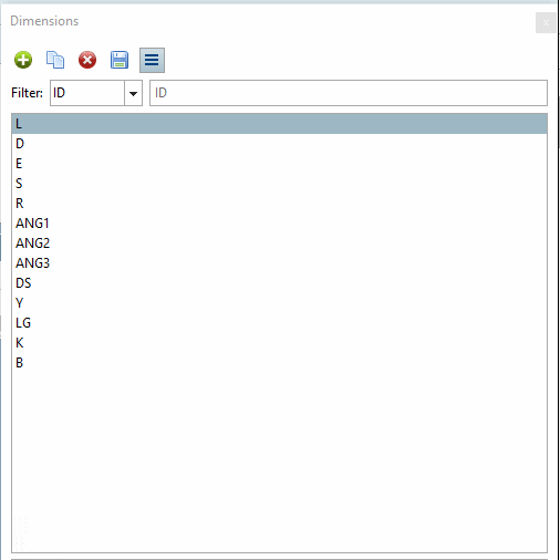
L'area di lavoro è la finestra di aggancio di Dimensioni [Dimensionings]. È suddivisa in due aree di dialogo:
L'area di dialogo superiore elenca tutte le dimensioni con il relativo testo di descrizione (idealmente il nome della variabile come L, R, D, ecc.), mentre l'area di dialogo inferiore elenca in dettaglio i parametri della dimensione selezionata.
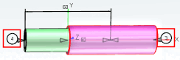
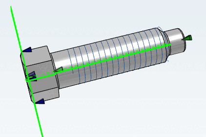
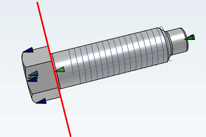
Quando si seleziona una quotatura, la quotatura corrispondente è evidenziata inverde nella vista 3D [3D view] e il punto iniziale [Start point] e finale [End point] della quotatura sono evidenziati in rosso. Al contrario, facendo clic su una quotatura nella vista [3D view] 3D si evidenzia la linea corrispondente sulla destra.
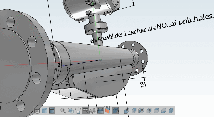
Non appena sono stati impostati tutti i parametri obbligatori [Mandatory parameters], il dimensionamento viene immediatamente visualizzato nella vista 3D [3D view].
Non appena vengono impostati tutti i parametri obbligatori [Mandatory parameters], le dimensioni sono immediatamente visibili anche nella derivazione 2D [2D derivation].
Facendo clic su una linea di quotatura, nell'area di dialogo inferiore vengono elencati tutti i parametri della quotatura, suddivisi in parametri obbligatori [Mandatory parameters], parametri opzionali [Optional parameters] e parametri 3D [3D Parameter]. Questi ultimi possono essere creati o semplicemente modificati. Le modifiche sono immediatamente visibili nella vista 3D [3D view] (purché i parametri obbligatori siano disponibili).
Informazioni dettagliate sui parametri obbligatori si trovano nei singoli capitoli dei tipi di quotatura. Sezione 7.16.7, “ Dettagli dei parametri opzionali ” Le informazioni dettagliate sui parametri opzionali sono riportate in un capitolo a parte.
Le modifiche ai valori vengono contrassegnate una volta nella parametri stessi per mezzo di un
 icon di annullamento (cliccando sull'icona si cambierà il
annullato) e nell'elenco delle dimensioni con il rosso
Carattere in grassetto.
icon di annullamento (cliccando sull'icona si cambierà il
annullato) e nell'elenco delle dimensioni con il rosso
Carattere in grassetto.Il L'icona Annulla viene mostrata finché non hai ancora salvato le modifiche usando l'icona Salva
 [Save changes] icona. Dopo di ciò, Undo non è più
Possibile.
[Save changes] icona. Dopo di ciò, Undo non è più
Possibile.
Sopra l'elenco delle dimensioni sono disponibili i seguenti pulsanti:
 Nuovo dimensionamento
Aggiungere [Create new dimension]
Nuovo dimensionamento
Aggiungere [Create new dimension]
-> Una nuova quota viene immediatamente aggiunta all'elenco delle quote. Il tipo [Type] ORIZZONTALE appare automaticamente. Se necessario, regolare la selezione nel campo elenco alla voce Tipo. È possibile modificare il tipo [Type] in qualsiasi momento.
 dimensionamento
duplicare [Duplicate dimension]
dimensionamento
duplicare [Duplicate dimension]
-> Viene creata una copia di una quotatura selezionata nell'elenco.
 Attualmente selezionato
Eliminare la dimensione [Delete selected dimension]
Attualmente selezionato
Eliminare la dimensione [Delete selected dimension]
–> La quota selezionata viene estratta dal Lista rimossa. Solo quando vengono apportate modifiche salva [Save changes]
è stato cliccato, l'eliminazione è completa e
non c'è più "tornare indietro".
-
modifiche
salvare [Save changes]
–> modifiche vengono visualizzate nel file
*.dimsalvato.Finché non devi usare il pulsante Salva le modifiche [Save changes]
è stato salvato è indicato dalla riga ID in alto
e per ogni parametro modificato visualizzata un'icona, che è possibile utilizzare per modificare il
Annulla l'azione in questione.
Una volta salvate le modifiche, non è più possibile ripristinarle.

[113] Un algoritmo [Attribute algorithm] come "VARIABLEX=TRANSLATE(VARIABILE) NON deve essere utilizzato in questo caso.