In the following you can see how to classify a conveyor belt and to test the simulation in the Mechatronics Concept Designer.
![[Note]](https://webapi.partcommunity.com/service/help/latest/pages/en/3dfindit/doc/images/note.png) | Note |
|---|---|
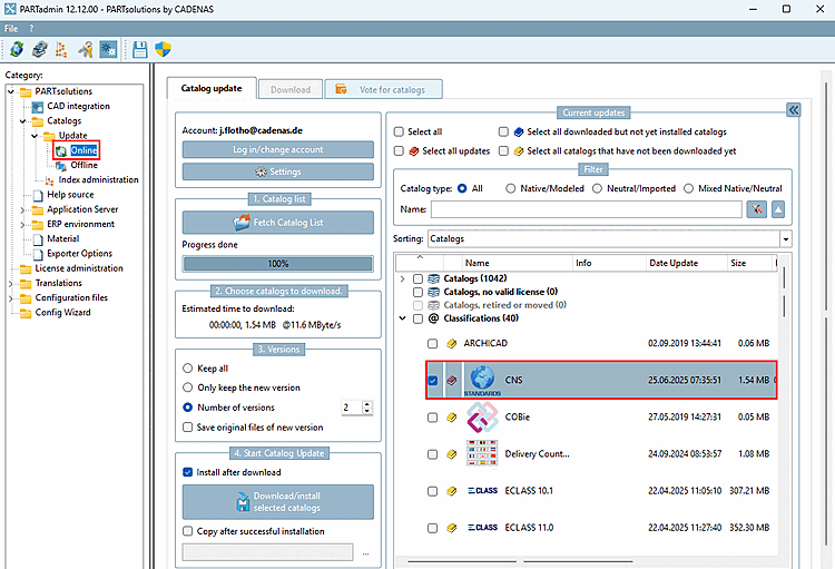
A current CNS classification is required. Install this in PARTadmin under Catalog update -> Online -> Select classifications.
| |
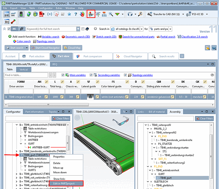
In the configurator [Configurator], select the individual part to be classified in the assembly (the belt in the case of a conveyor belt) and open it using the context menu command in PARTproject.
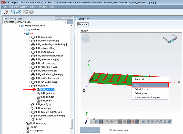
Select the 3db file on the left under Project selection.
-> The preview [Preview] appears on the right under Edit project (in this example, the belt).
Call up the context menu command Surface [Face] on the feature to be classified (here a surface).
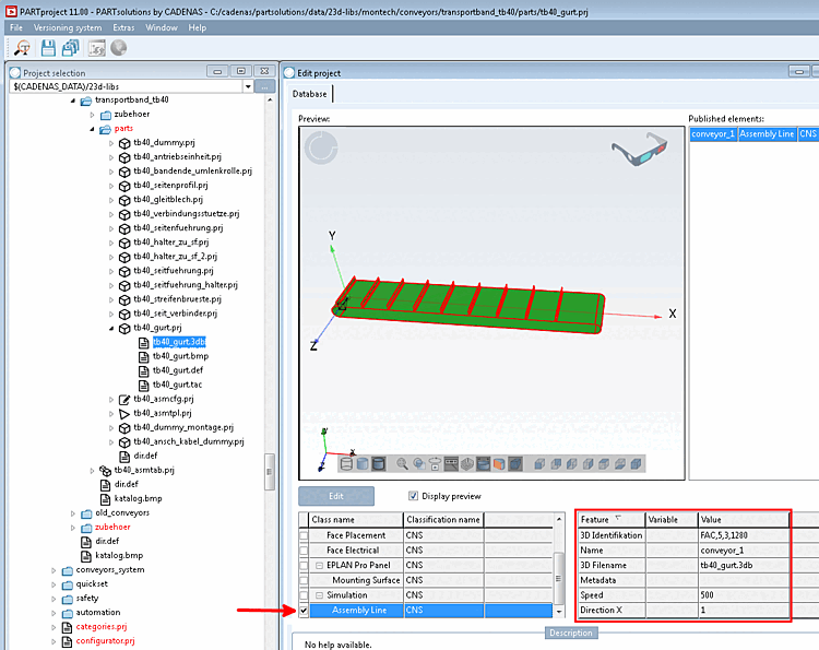
In the case of a conveyor belt, select the class under Simulation -> Assembly Line.
-> The individual characteristics are displayed to the right of the selected class.
In the case of a conveyor belt please set the following values:
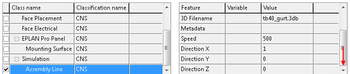
Direction: Direction vector for the conveyor. This must be parallel to the conveyor belt surface. Set X to 1 and Y and Z to 0.
Scroll down to see the parameters at the end of the list.
The values for 3D identification and 3D file name are set automatically. Metadata can remain empty.
Export the conveyor belt to NX by clicking on
 .
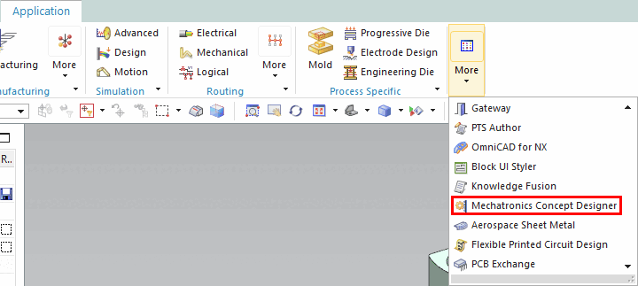
.Open the Mechatronics Concept Designer in NX under Application -> More.
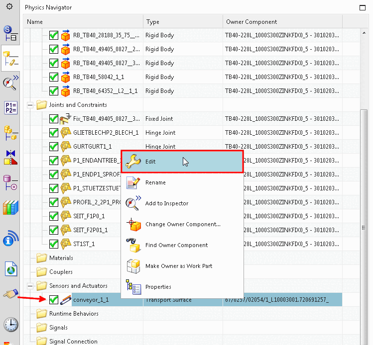
-> Under Sensors and actuators you can see the classified transport area.
Click on Edit in the context menu.
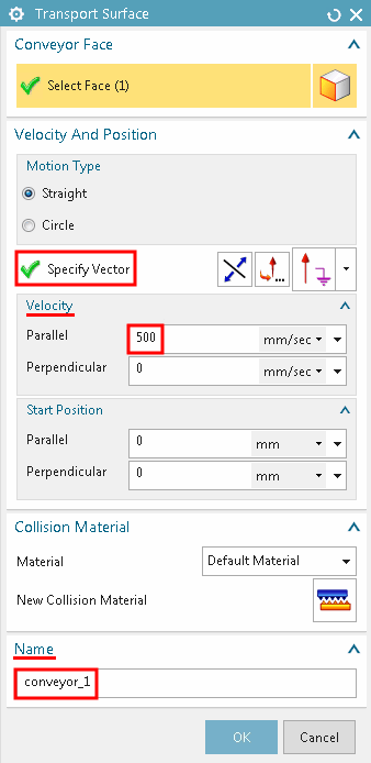
-> The Transport area dialog box opens.
As you can see, the vector, speed and name have been taken from the classification.
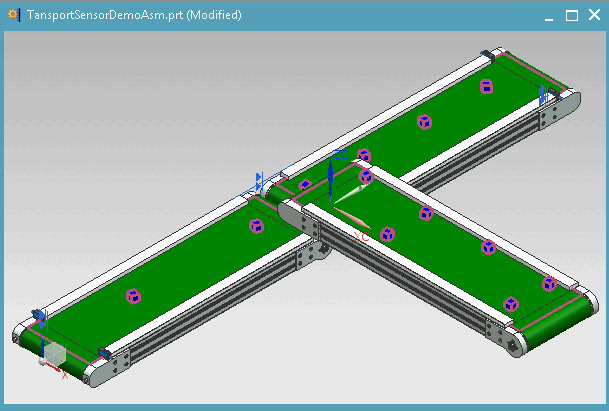
In addition, place a test object on the conveyor belt and start the simulation by clicking on the “Start” button
 .
.