
The measurement dialog [Measure dialog] is divided into the fields Element 1, Element 2 and Result and Fixings [Constraints].
Mit dem Aufruf des Befehls Measure erhält der Mauszeiger in der 3D view ein objektbezogenes Geometriesymbol , das die Art des jeweils berührten Elements anzeigt.
After you have clicked on two drawing elements (surface, edge, hole, etc.) in succession within the 3D preview [Preview 3D], an icon [Symbol] appears in the Element 1 and Element 2 fields.
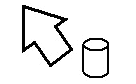
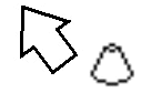
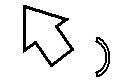
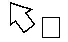
Hier ein Überblick über die möglichen Geometriesymbole:
![[Note]](https://webapi.partcommunity.com/service/help/latest/pages/en/3dfindit/doc/images/note.png) | Note |
|---|---|
The quickest way to determine the dimensions of a component is in the context menu of the 3D window via the menu item Measurement grid [Measuring grid]. See also Section 7.7.3, “Toolbar Buttons”. | |
In the following example, two opposite surfaces are clicked.
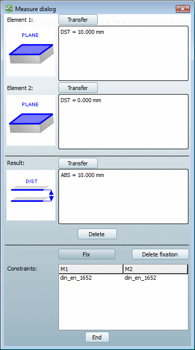
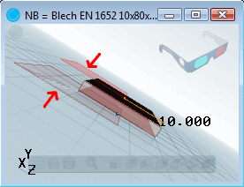
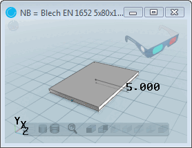
Die beiden Flächen befinden sich in einem Abstand von 10 mm, was im Feld Result symbolhaft dargestellt ist. Das Maß des Abstands (ABS = 10.000 mm) erscheint rechts davon.
The command is available for planar, parallel surfaces.
When changing the table row, the display of the dimensions in the 3D preview [Preview 3D] is retained.
With you can delete the fixation.
The command is required for classifying native parts.
Detailed information on this can be found under Transferring values from the Measurement dialog box.