![[Note]](https://webapi.partcommunity.com/service/help/latest/pages/en/3dfindit/doc/images/note.png)
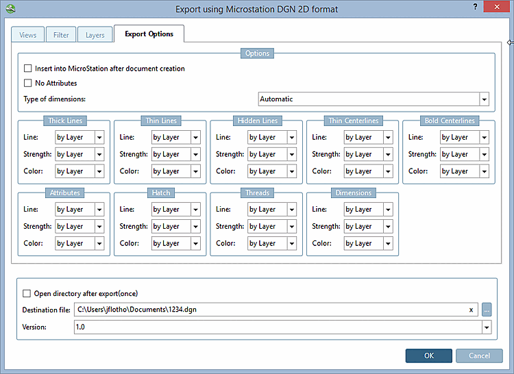
Then insert into the active MicroStation application [Insert into MicroStation after document creation]:
Do not generate attributes [No Attributes] ...prevents certain attributes (e.g. texts from PARTproject) from being transferred to the CAD system during export.
Type of dimensions [Type of dimensionings]:
If a symbolic dimensioning can be created then it is used, otherwise the exploded.
Symbolic dimensions [Only symbolic dimensions] only:
A dimensioning created in eCAT for the component or a dimensioning created in the PARTdataManager before the export is recognized as such.
When using this option the dimensioning is created as "real" dimensioning. After selection the respective dialog is displayed.
Resolved dimensions [Only exploded dimensionings] only:
Dimensioning and text are only displayed as exploded elements.
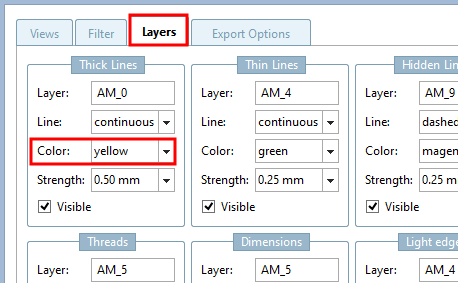
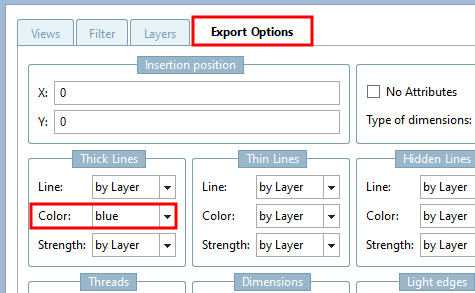
In addition to the option of specifying certain lines and colors directly, you can also make the color and line setting dependent on the layer setting in the CAD system. To do this, select the "by layer " setting.
![Levels [Layers] " tab page - Microstation DGN 2D](https://webapi.partcommunity.com/service/help/latest/pages/en/3dfindit/doc/resources/img/img_541b821c1a0c4cb79ac59c146d517477.png)