Each dimensioning must contain the following parameters:
ID is only required if a dimensioning serves as the base dimension [Base dimension] for a subsequent dimensioning.
The description text is displayed at the top of the list. Initially, a description is automatically assigned when a new dimensioning is created (AUTO-<number>), but you can customize this as required.
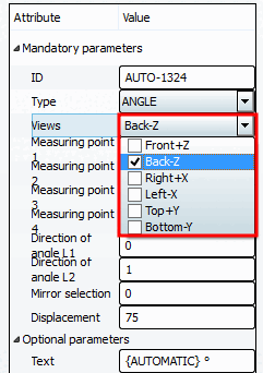
When creating a new dimension, HORIZONTAL appears automatically. Adjust the selection in the list field to ANGLE. You can change the type at any time.
Activate the checkbox for the desired 2D views on which the dimensioning is to be displayed.
Views that contain a dimensioning can be recognized in the 3D toolbar by a corresponding icon with a dimensioning line
 .
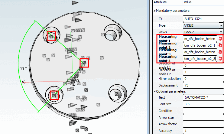
.Measuring point 1, measuring point 2, measuring point 3, measuring point 4
At angular dimensionings 2 lines are specified by 4 points, which describe the angle.
Direction of rotation [Direction of angle] L1 and direction of rotation [Direction of angle] L2
Direction of rotation of line 1 and 2
The arc is drawn from line 1 to line 2. Thus please regard the order when setting the points and lines. Possibly change the measuring points 1/2 with 3/4. Changing of points and lines influences the direction of rotation of the angle.
Shifting [Displacement] the dimension arc of the angle from the intersection of the lines
Specify a fixed value or better a variable or use a PARTdesigner expression as well: E.g.: D*2
![[Note]](https://webapi.partcommunity.com/service/help/latest/pages/en/3dfindit/doc/images/note.png)