The following overview on optional parameters applies for all types of dimensioning and annotation:
Text can be created in different ways:
{AUTOMATIC}: An automatically generated measurement value (default)
{AUTOMATIC}Delete the expression "{AUTOMATIC}" and enter the desired text.
Any text combined with an automatically generated value of dimensioning
The degree symbol shall be displayed in addition to the value of dimensioning.
{AUTOMATIC} °Any PARTdesigner expressions can be used.
E.g. {partname@variable}: Part name with declaration of variable
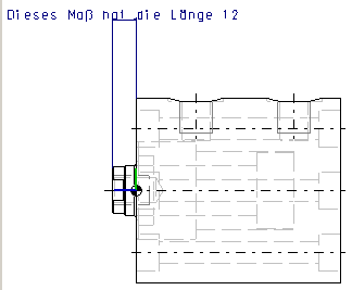
Dieses Maß hat die Länge {RZ500@D}If the automatic calculation of the numerical value does not result in a satisfactory rounding (9.99999), you can use PARTdesigner-Expressions (see Section 10.1, “PARTdesigner-Expressions ”) to select a different calculation (e.g. round, shorten).
You can also convert from inch to mm and display the unit in addition.
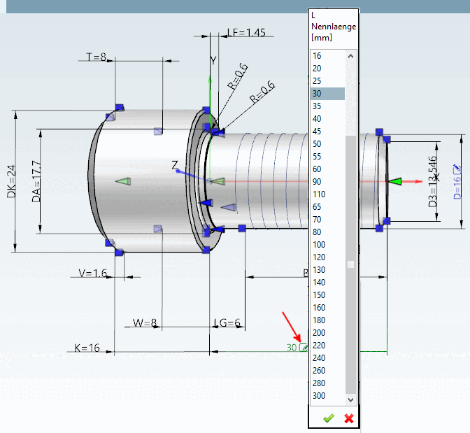
Enter the desired variable here, which should later be editable for user input. Ideally, use the same name that you used under Description. As soon as an entry has been made, the corresponding icon is displayed in the 3D view
 .
.By clicking on the icon
icon, you can adjust the characteristics directly in the 3D view.Section 2.1.7.6.6, “Change characteristic via dimension labels ” in PARTsolutions - User comparisons under Section 2.1.7.6.6, “Change characteristic via dimension labels ” in PARTsolutions - User
If the specification is omitted, 3. 5 is set by default. The unit corresponds to the drawing unit.
Alternatively you can use PARTdesigner Expressions.
15*RZ500@D/20
You can use all PARTdesigner expressions for this. See Section 10.1, “PARTdesigner-Expressions ” Section 10.1, “PARTdesigner-Expressions ”
IF SHORTVIEW@HUB2D=0 THEN AUTOMATIC ELSE AUTOMATIC+HUB-SHORTVIEW@HUB2D ENDIF
IF SHORTVIEW@HUB2D=0 THEN AUTOMATIC ELSE H2 ENDIF
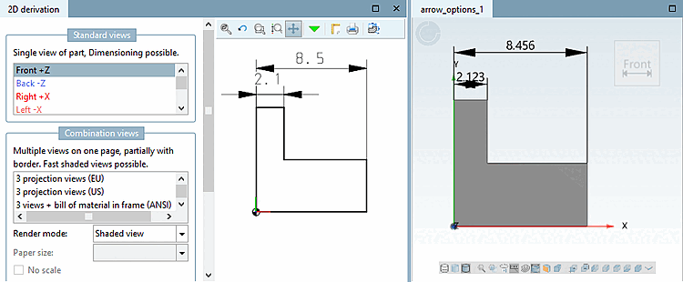
=> font size [Font size] 3.5 and arrow size [Arrow size] = 3.5 => "normal" arrow size
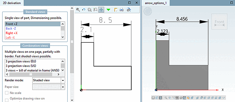
=> font size [Font size] 3.5 and arrow size [Arrow size] = 1 => "normal" arrow size
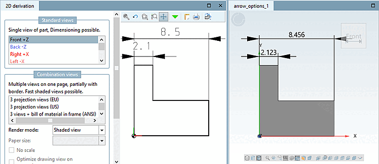
=> Font size 3.5 and arrow size [Arrow size] = 1 => Arrow size additionally controllable via arrow factor [Arrow factor]
The user interface has been made clearer with V10. There is only one value to be entered under "Arrow size [Arrow size] ". This is applied as a factor to the "Font size [Font size] " if the "Arrow factor [Arrow factor] " option is activated.
Arrow factor activated: The value under Arrow size [Arrow size] is interpreted as a factor. The font size (if no value is entered, 3.5 is used automatically) is multiplied by the factor.
The input may be a simple value.
0.5
Alternatively, the specification can be made with PARTdesigner-Expression.
15*RZ500@D/20
Arrow factor [Arrow factor] deactivated: The value under Arrow size is used according to the "old" proportionality of font size [Font size] and arrow size [Arrow size].
All statements concern the automatic dimensioning described here, but not the interactive dimensioning via toolbar.
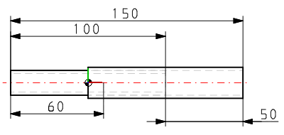
With this function you can flip arrows to the other side of dimensioning lines while text is kept centered at the same time (due to lack of space).
In 3D, arrows and text are inside the dimensioning lines.
In 2D as well. However, when there is a lack of space the arrows will automatically switch to the outside.
This behavior corresponds to that of previous versions both in 3D and 2D.
Keep in mind that this depiction is basically used in previous versions.
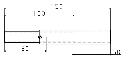
Hold [Keep position] page: Arrows keep their position in any case, both in 3D and 2D.
Change page [Flip side]: The arrows switch to the other page, the text remains centered, both in 3D and 2D.
The value specifies how accurate a numerical value on the dimensioning arrow has to be.
![[Note]](https://webapi.partcommunity.com/service/help/latest/pages/en/installation/doc/images/note.png)
![The user interface has been made clearer with V10. There is only one value to be entered under "Arrow size [Arrow size] ". This is applied as a factor to the "Font size [Font size] " if the "Arrow factor [Arrow factor] " option is activated.](https://webapi.partcommunity.com/service/help/latest/pages/en/installation/doc/resources/img/img_0471f534039b426981c3c337ea9f508e.png)
![New "Arrow page [Arrow position] " option](https://webapi.partcommunity.com/service/help/latest/pages/en/installation/doc/resources/img/img_05934bca42864e25b99b73940a0d147e.png)