Insertion lines can be used for moving elements. For example, for connectors of profiles that move in a groove.
Insertion lines are created from a combination of a "normal" connection point and an absolute level.
Creating the connection point (line)
|
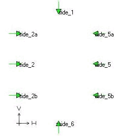
Create a new sketch on the absolute level and insert the desired connection points.
|
|
![[Note]](https://webapi.partcommunity.com/service/help/latest/pages/en/installation/doc/images/note.png)
![Change parameters [Change parameter]](https://webapi.partcommunity.com/service/help/latest/pages/en/installation/doc/resources/img/img_75c4526641f340ddb3ea3bc598a7a091.png)
|
Insertion lines are marked with the familiar pyramid symbol and also with a green line at the base of the pyramid. |
|
Create absolute plane in connection to the connection point
![[Important]](https://webapi.partcommunity.com/service/help/latest/pages/en/installation/doc/images/important.png)
![Absolute level [Fixed plane]](https://webapi.partcommunity.com/service/help/latest/pages/en/installation/doc/resources/img/img_6533ccb0d293428b8d8cda5566ed33fa.png)
|
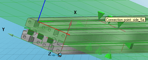
In the 3D preview, the green coordinate axis indicates the insertion line [Connection line] . The pyramid symbolwhich is used for connection points in the 3D preview, is used identically for insertion lines.
|
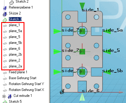
Naming convention Plane - insertion line
The name of the plane must be plane_<side_nr>.
In other words, the numerical value of a level corresponds to the numerical value of the corresponding connection point (insertion line):
plane_1 <-> side_1, plane_5a <-> side_5a, etc.
The sum of the numerical values of the opposite connection points must be the same in each case. (Here in the example: 1+6, 2+5, the sum is 7 in each case).