Group tools: The tools in the Sketcher are grouped by default. You can access the sub-items by clicking on the small black arrow.
Call up parameter dialog after object creation [Call dialog for parameters after generating]: Default is switched off.
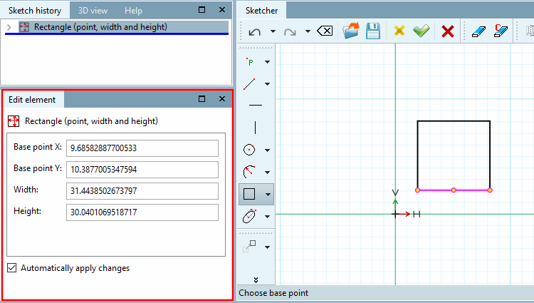
As soon as a design step has been executed, the individual parameters are displayed in the Edit element docking window.
If you want the Change parameters [Change parameter] window to appear after each design step (old behavior as in V11), you must activate this option. The Edit element docking window is then not used.
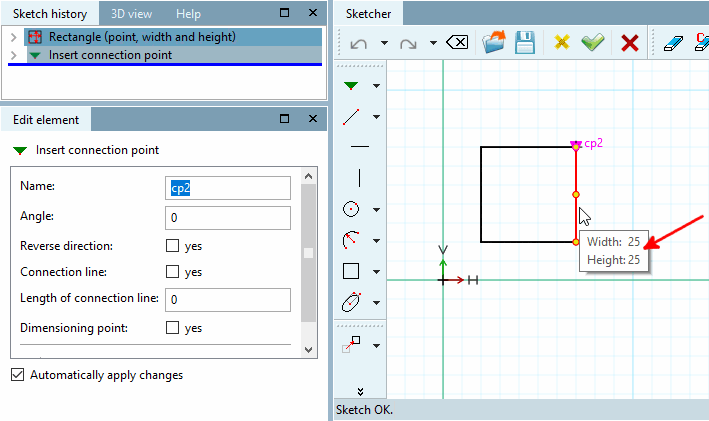
Show connection point names in workspace [Show connection point names in working area]: Yes/No
Show tooltips in work [Show tool tips in working area] space:
Displays the tooltips (brief information) for the selected drawing element.
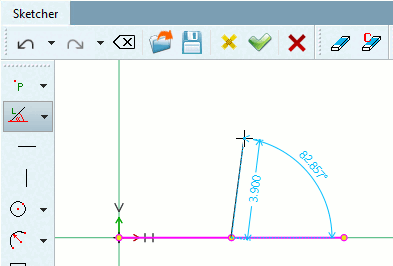
Show auxiliary dimensioning [Show live dimensions]:
When drawing lines or angles, lives dimensions on line length, circle diameter or angles between lines are shown.
The color of the auxiliary dimension [Live dimensions] can be adjusted in the Color settings dialog area.
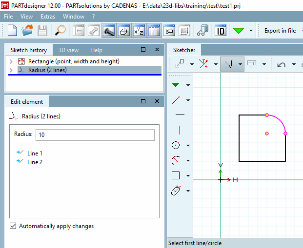
Show reference points: Reference points can be helpful as they can be reused for further design steps. You can use the options in the list field to control the display for individual tool types.
Remember half-length value [Keep half-length value]: Affects the preset half-length [Half-length] for insert vertical [Vertical line] and insert horizontal [Horizontal line].
Maximum [Max. number of intersection points] size of the intersection list:
This option applies in particular to the Matrix copy
 command, which - by creating numerous copies - can quickly result in an immense number of intersections.
To every intersect point, a certain calculation effort is connected, which requires storage space, which is why a limit for calculated intersect points is set in this field. If the set upper limit of the calculated intersect points is exceeded, the intersect points in the sketch are visible themselves, however their calculated value is no longer accounted for in the system.
Concretely, this means that the so-called object snap for intersect points can no longer be displayed above the upper limit.
Number of decimal places for dimensions: currently without function
Default setting for dimension height [Default dimension text height]: currently without function
Reduce sketch history if Sketcher [Reduce sketch history on applying Sketcher (experimental)] has been accepted (experimental):
Many sketches are more complicated than necessary.
In Sketcher itself you will find the function
 Reduce sketch (experimental). It reduces the steps of a sketch as far as possible. It is best to always use the function manually via a button in the Sketcher.
Via settings option, the function should only be used for frequent use (as the calculation needs some time).
If a message appears after execution History element ... is not constant means that the sketch uses variables. These cannot be reduced.
If a sketch only contains a circle or rectangle, meaning all steps are relevant, it also cannot be reduced.
Otherwise it is shown to how many elements it can be reduced.