5.12.11.31. Classify
Electrical Parts - Tutorial 5.12.11.31.8.
Mounting
Description (CNS_CP|4|7)
|  |
| Prev | Next |
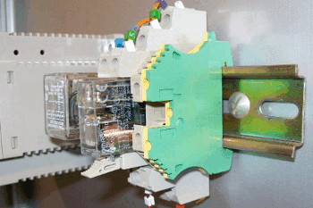
Mounting Point describes where other components can be attached to the component.
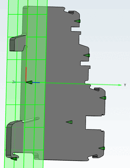
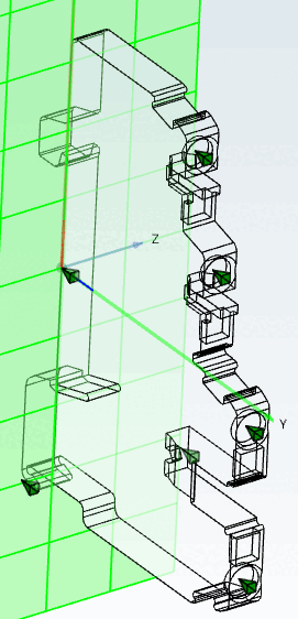
Mounting Description describes the position and orientation of a part to which it can be attached to a compatible component (DIN mounting rail, directly on the PCB, etc.). For this reason, the attachment point must be positioned correctly, otherwise the component will be misaligned.
![[Note]](https://webapi.partcommunity.com/service/help/latest/pages/en/partsolutions_admin/doc/images/note.png)
For rails the following must be observed:
The setting of a mounting description is described below.
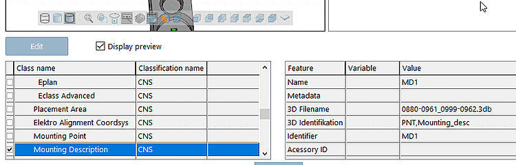
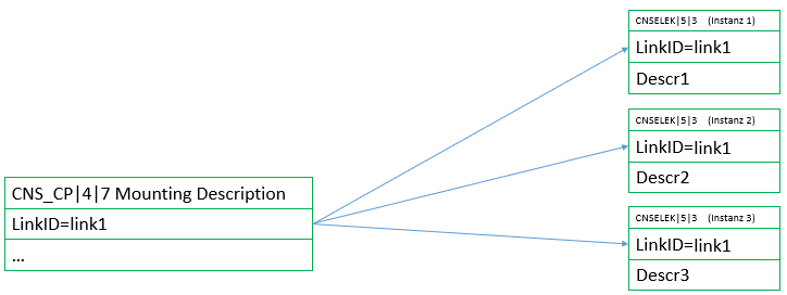
Classify the connection point as a mounting description (CNS_CP|4|7 ). (Preferably an attachment point was created specifically for this purpose)
In particular, enter a value for the Link ID feature.
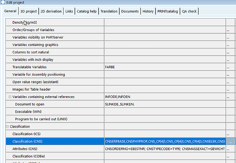
Save the current progress and switch to PARTproject to the General tab page.
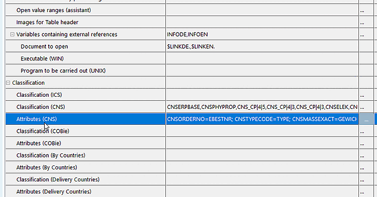
Open Classification (CNS) here.
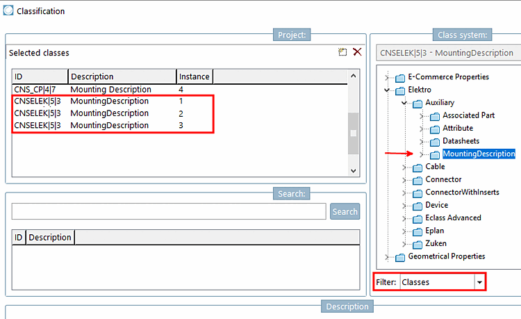
Set the Classes option in the filter [Filter] and add the required number of associated instances (1,2,3,4,...) under Electro -> Auxiliary by double-clicking on the Mounting Description class (CNSELEK|5|3 ).
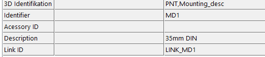
In the Link ID characteristic, enter the same value that you have already assigned in the Mounting Description class (CNS_CP|4|7 ).
Enter the name under Description, which must match the corresponding value under Mounting Point -> Description.
In this example, the value TS35 is the mounting type of the component (TS35 = DIN mounting rail 35mm).
![Example in the "Class variables [Class variables] " dialog](https://webapi.partcommunity.com/service/help/latest/pages/en/partsolutions_admin/doc/resources/img/img_760099e6905744e788f5b0011a1f2e95.png)