
![Modify -> Crop [Trim] grouped (part 2)](https://webapi.partcommunity.com/service/help/latest/pages/en/partsolutions_user/doc/resources/img/img_f29d3464fa2b453e9da0295b33f9b137.png)
![[Note]](https://webapi.partcommunity.com/service/help/latest/pages/en/partsolutions_user/doc/images/note.png)
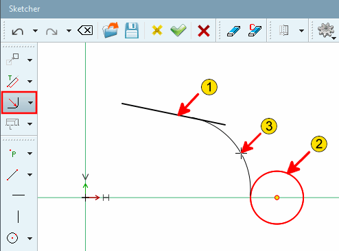
Create fillets

![Radius with 2 elements [Radius with 2 elements]](https://webapi.partcommunity.com/service/help/latest/pages/en/partsolutions_user/doc/resources/img/img_86fb6f821d4d4045b298d55acf8a6f39.png)
![Rounding on 2 elements [Radius with 2 elements] - Radius: 3](https://webapi.partcommunity.com/service/help/latest/pages/en/partsolutions_user/doc/resources/img/img_5b5c60d67c75475084700e5756fdd632.png)
| ||||
 Chamfer at 2 lines defined by angle at distance from
intersection [Chamfer at 2 lines defined by angle at distance from intersection]
Chamfer at 2 lines defined by angle at distance from
intersection [Chamfer at 2 lines defined by angle at distance from intersection]
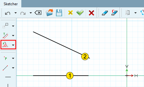
Chamfer between 2 lines, adjustable via the angle [Angle] to the first selected line or a distance [Distance] defined as shown in the figure below.
Chamfer at 2 lines defined by angle at distance from intersection [Chamfer at 2 lines defined by angle at distance from intersection]
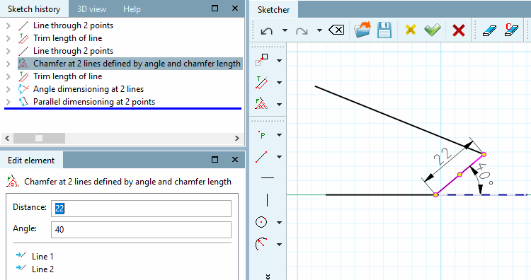
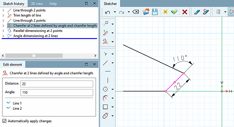
 Chamfer at 2 lines defined by angle and chamfer
length [Chamfer at 2 lines defined by angle and chamfer length]
Chamfer at 2 lines defined by angle and chamfer
length [Chamfer at 2 lines defined by angle and chamfer length]
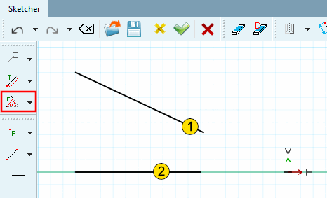
Chamfer between 2 lines, adjustable via angle on first selected line (counterclockwise) and length of chamfer.
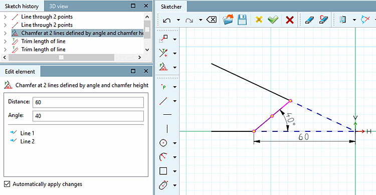
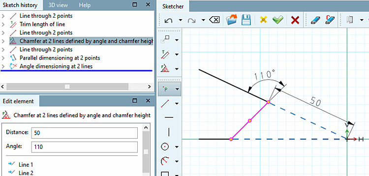
 Chamfer at 2 lines defined by angle and chamfer
height [Chamfer at 2 lines defined by angle and chamfer height]
Chamfer at 2 lines defined by angle and chamfer
height [Chamfer at 2 lines defined by angle and chamfer height]
Chamfer between 2 lines adjustable via angle on first selected line (counterclockwise) and distance between chamfer and intersection of both lines.
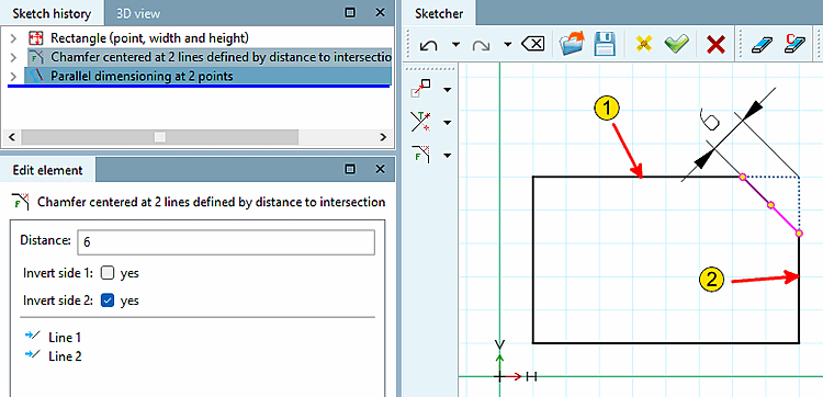
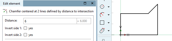
 Chamfer centered at 2 lines defined by distance to
intersection [Chamfer centered at 2 lines defined by distance to intersection]
Chamfer centered at 2 lines defined by distance to
intersection [Chamfer centered at 2 lines defined by distance to intersection]
45° chamfer between 2 lines, adjustable via the chamfer's distance to the (imaginary) intersection of both lines.
Select distance above point [Select distance by point]: Click anywhere in the area of the chamfer to be created.
In the input field under Spacing [Distance], adjust the desired spacing in the Edit element docking window.
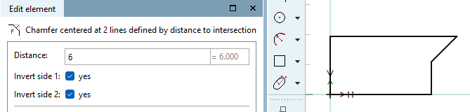
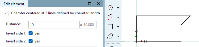
Optional: It is also possible to place the chamfer outside the outlined body:
Activate or deactivate the checkboxes under Invert page 1 [Invert side 1] and Invert page 2 [Invert side 2] accordingly.
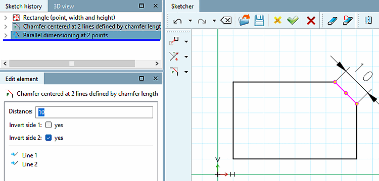
 Chamfer centered at 2 lines defined by chamfer
length [Chamfer centered at 2 lines defined by chamfer length]
Chamfer centered at 2 lines defined by chamfer
length [Chamfer centered at 2 lines defined by chamfer length]
45° chamfer between 2 lines, adjustable via the length of the chamfer.
Select distance above point [Select distance by point]: Click anywhere in the area of the chamfer to be created.
Determine the exact length of the chamfer in the Edit element window.
Optional: It is also possible to place the chamfer outside the outlined body:
Activate or deactivate the checkboxes under Invert page 1 [Invert side 1] and Invert page 2 [Invert side 2] accordingly.
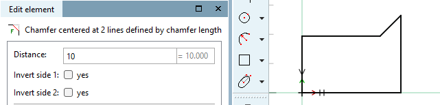
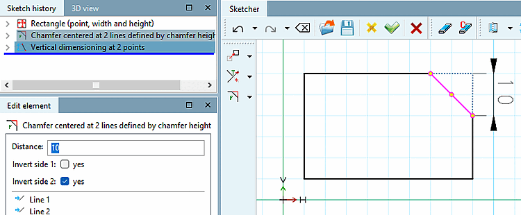
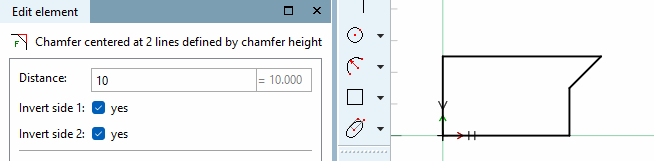
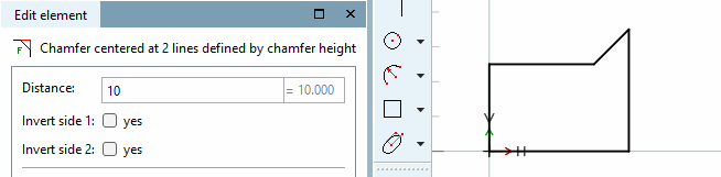
 Chamfer centered at 2 lines defined by chamfer
height [Chamfer centered at 2 lines defined by chamfer height]
Chamfer centered at 2 lines defined by chamfer
height [Chamfer centered at 2 lines defined by chamfer height]
45° chamfer between 2 lines, adjustable via the chamfer's length of indentation.
Select distance above point [Select distance by point]: Click anywhere in the area of the chamfer to be created.
Determine the exact feed length in the Edit element docking window.
Optional: It is also possible to place the chamfer outside the outlined body:
Activate or deactivate the checkboxes under Invert page 1 [Invert side 1] and Invert page 2 [Invert side 2] accordingly.
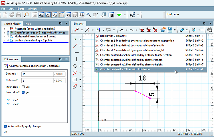
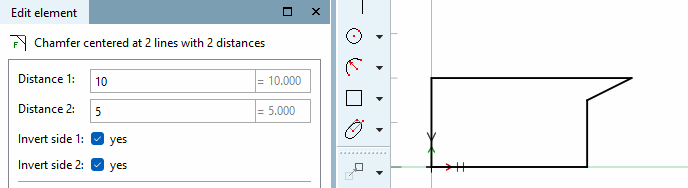
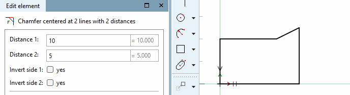
 chamfer in the middle of 2 lines across
2 feed lengths [Chamfer centered at 2 lines with 2 distances]:
chamfer in the middle of 2 lines across
2 feed lengths [Chamfer centered at 2 lines with 2 distances]:
Select the feature chamfer centered on 2 lines over 2 feed lengths [Chamfer centered at 2 lines with 2 distances].
Select distance via point [Select distance by point]: Determine the distance 1 [Distance 1] and distance 2 [Distance 2] in the Edit element docking window.
Optional: It is also possible to place the chamfer outside the outlined body:
Activate or deactivate the checkboxes under Invert page 1 [Invert side 1] and Invert page 2 [Invert side 2] accordingly.
![Chamfer at 2 lines defined by angle at distance from intersection [Chamfer at 2 lines defined by angle at distance from intersection]](https://webapi.partcommunity.com/service/help/latest/pages/en/partsolutions_user/doc/resources/img/img_5d4c48d0eb04476daadb6ef778354dfb.png)
| ||||