
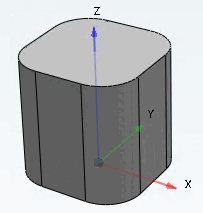
This group allows determining the initial shape and alignment of the pipe (see following figures).
![Initial cross-section [Initial cross section] -> circle [Circle]](https://webapi.partcommunity.com/service/help/latest/pages/en/partsolutions_user/doc/resources/img/img_de562a91182449fa9f76d4fbda611e41.png)
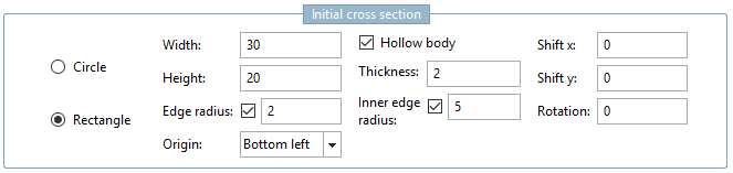
![Initial cross-section [Initial cross section] -> rectangle [Rectangle]](https://webapi.partcommunity.com/service/help/latest/pages/en/partsolutions_user/doc/resources/img/img_b88d3fc1a93a4cf5af4e068f51154ec2.png)
Error index: If the icon
 icon is visible, there are errors in this group. If you move the mouse pointer over the icon, a tooltip is displayed with the exact name of the error.
Cross-section type: Choose between circle [Circle] and rectangle [Rectangle].
Cross-section input fields: The corresponding input fields are displayed depending on the selection of the cross-section type:
Width / Height: Determine the width and height of the initial cross-sectional area.
Edge radius: This option can be used to round the corners. Activate the option and enter the radius of the rounding in the input field.
The rounding is not visible in the preview, but only in the real display confirmed with OK.
Origin: Center, Bottom left (default), Top left, Bottom right, Top right
If the Hollow body option is activated, the input field for wall thickness [Thickness] is activated. The wall thickness entered must be less than the radius or half the width and height. The error icon will appear if an invalid entry has been made.
Edge radius inside [Inner edge radius] can also be activated.
Alignment: The pipe can initially be moved in the x and y direction (shifted x [Shift x] / shifted y [Shift y] ). The default value "0" places the pipe in the center of the selected plane.
Rotation, the pipe will initially rotate around itself. The value "0" means no rotation.
![Tube with " edge radius [Edge radius] " (outside) and "edge radius inside [Inner edge radius] "](https://webapi.partcommunity.com/service/help/latest/pages/en/partsolutions_user/doc/resources/img/img_2f5c0227fc004ad487f31d99d26f5731.png)
Each input field of this group allows table and/or local variables and expressions (only common PARTdesigner expressions, see Section 10.1, “PARTdesigner-Expressions ”