7.13.5.7.3. Context menu
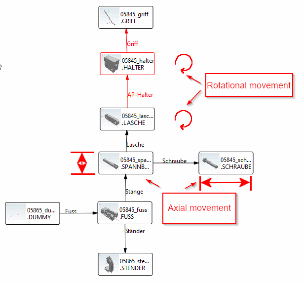
Attachment Point: Examples 7.13.5.7.3.2. Combined
Rotary and axial movements / assembly setup |  |
| Prev | Next |
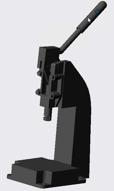
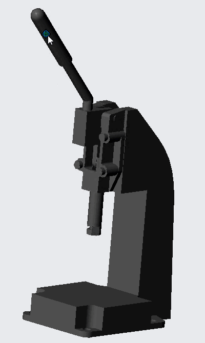
Example a combined rotary and axial movement
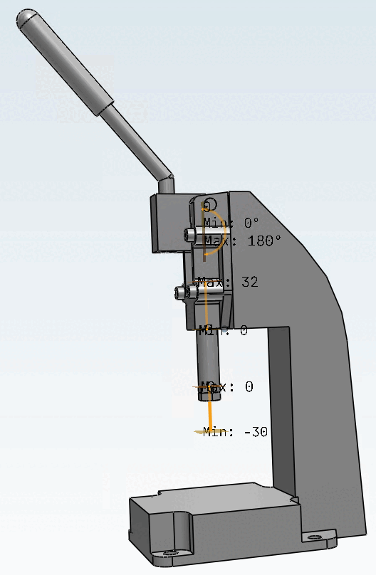
The rotary lever at the top moves the ram axially over a defined STROKE.
The assembly must be can be designed in such a way that the axial and rotary motion in the CAD functioned.
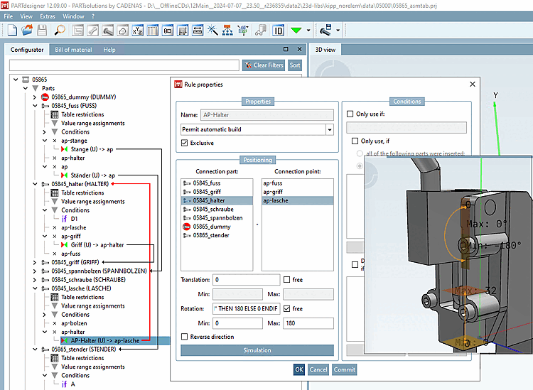
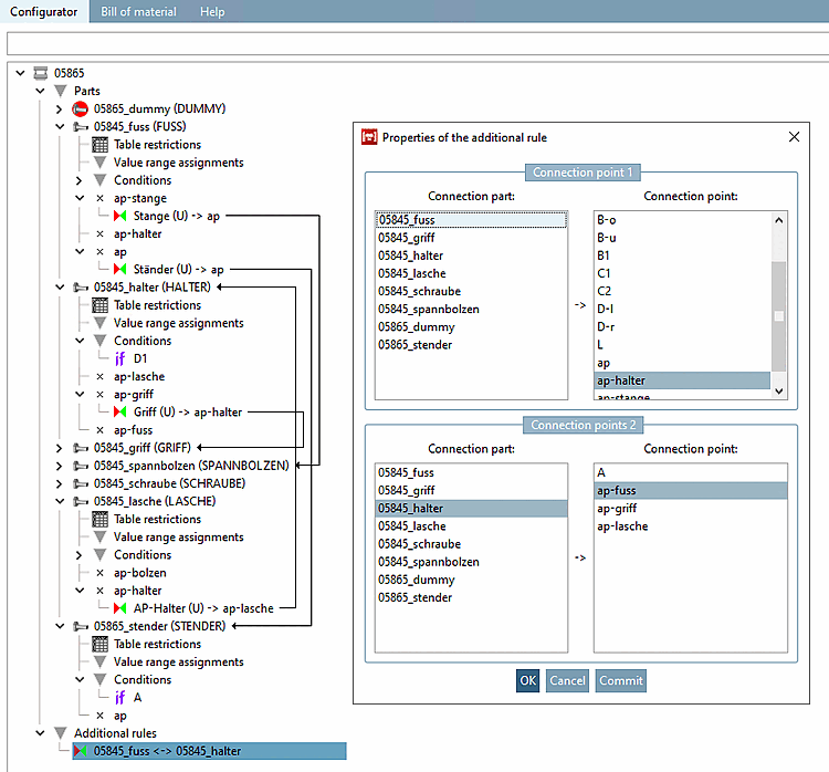
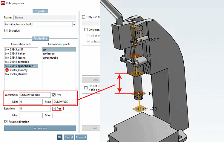
Characteristics of the rule [Rule properties]: Foot on Clamping bolts
To this end, In this example , Translation "Free" (0 to MAX).
![[Important]](https://webapi.partcommunity.com/service/help/latest/pages/en/partsolutions_user/doc/images/important.png) | Important |
|---|---|
In the case of filming and axial movements, the rotation of axial motion must be CAD compatibility can also be set FREE. | |
Features of Rule [Rule properties]: Clamping Bolt on Tab with rotation FREE (without limits)
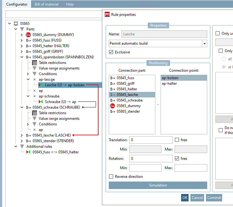
Features of the rule [Rule properties]: Tab on retaining arm with rotation FREE (with limits)
Rotation with Movement. The boundaries thus create the maximum mobility of the CAD Poor.