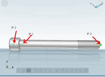
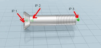
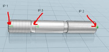
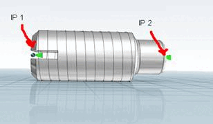
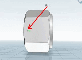
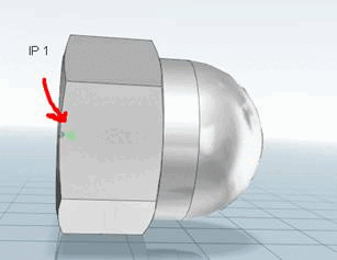
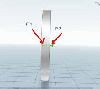
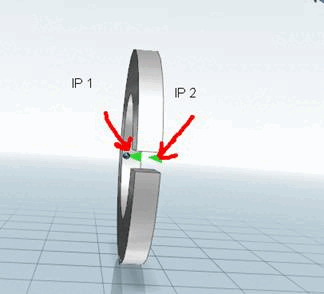
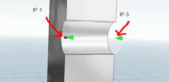
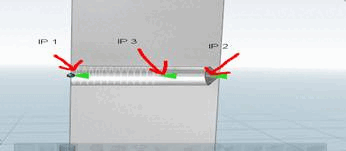
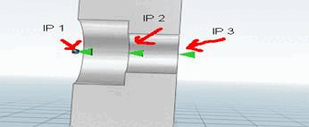
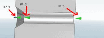
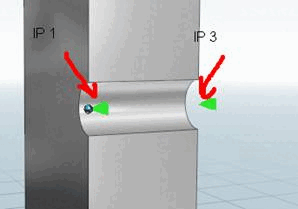
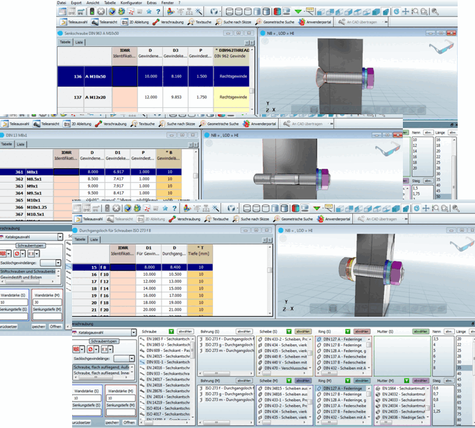
7.9.3.4.1.5. Connection points on screw connection elements

The following examples show what should be noted for connection points at connection elements.

Connection examples

Connection examples

[Note]Note

In general, the following applies: The number, position, alignment and naming (numbering) of the connection points must be observed!

Number, position and naming results from the PCon classification.

  • Screws:

    Cylinder head screw

    Cylinder head screw

    Attachment points [Connection points]:

    • IP 2: Top side of screw head

    • IP 1: Contact surface screw head

    • IP 3: Screw end

    Countersunk screw

    Countersunk screw

    Attachment points [Connection points]:

    • IP 1: Top side of screw head

    • IP 2: underside of screw head

    • IP 3: Screw end

    Stud bolt

    Stud bolt

    Attachment points [Connection points]:

    • IP 1: Top side

    • IP 2: Bottom side

    • IP 3: End of screw-in thread

    Grub screw

    Grub screw

    Attachment points [Connection points]:

    • IP 1: Top side

    • IP 2: Bottom side

  • Nuts

    Mother

    Mother

    Attachment point [Connection point]:

    • IP 1: Support surface

    Cap nut

    Cap nut

    Attachment point [Connection point]:

    • IP 1: Support surface

  • Discs / Rings

    Disk

    Disk

    Attachment points [Connection points]:

    • IP 1: Top side

    • IP 2: Bottom side

    Ring

    Ring

    Attachment points [Connection points]:

    • IP 1: Top side

    • IP 2: Bottom side

  • Drill holes

    Through-hole threaded hole

    Through-hole threaded hole

    Attachment points [Connection points]:

    • IP 1: Top side of material

    • IP 3: underside of material

    Blind hole threaded bore

    Blind hole threaded bore

    Attachment points [Connection points]:

    • IP 1: Top side of material

    • IP 2: underside of material

    • IP 3: Thread end

    Through-hole with counterbore, smooth surface

    Through-hole with counterbore, smooth surface

    Attachment points [Connection points]:

    • IP 1: Top side of material

    • IP 2: Lowering contact surface

    • IP 3: underside of material

    Through-hole for countersunk screws

    Through-hole for countersunk screws

    Attachment points [Connection points]:

    • IP 1: Top side of material

    • IP 2: End of subsidence

    • IP 3: underside of material

    Through hole

    Through hole

    Attachment points [Connection points]:

    • IP 1: Top side of material

    • IP 3: underside of material