The user interface is divided into a toolbar, menu bar and docking window:
At the top you can find the following menus:
View: See Section 7.19, “ View menu ”.
Extras: See Section 7.20, “ Extras menu ”.
Windows [Window]: See Section 7.21, “ Window menu ”.
Help: See Section 7.22, “ Help menu (?)”.
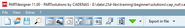
Below the menu bar you will find the standard toolbar and the export toolbar with the following buttons:
 New: See Section 7.18.1, “
New
”.
New: See Section 7.18.1, “
New
”. Open: See Section 7.18.4, “
Open
”.
Open: See Section 7.18.4, “
Open
”. Save: See Section 7.18.5, “
Save or Save as..”.
Save: See Section 7.18.5, “
Save or Save as..”.
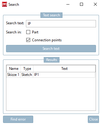
 Search for features and/or connection points in part/sketch
 Check part [Test part]: See Section 7.24.2, “
Test part
”.
Check part [Test part]: See Section 7.24.2, “
Test part
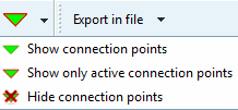
”.Connection points: Selection list to show or hide existing connection points in the component or to show only the active connection points
Export to file [Export in file]: See Section 2.1.8, “ Transfer to CAD (with and without interface) ” in PARTsolutions - User.


The main view consists of single docking windows.
![PARTdesigner with 3D history [3D History], 3D view, variable manager [Variable Manager] and table [Table]](https://webapi.partcommunity.com/service/help/latest/pages/en/3dfindit/doc/resources/img/img_e50bddda8ab34befa2170bbf1189dea3.png)
PARTdesigner with 3D history [3D History], 3D view, variable manager [Variable Manager] and table [Table]
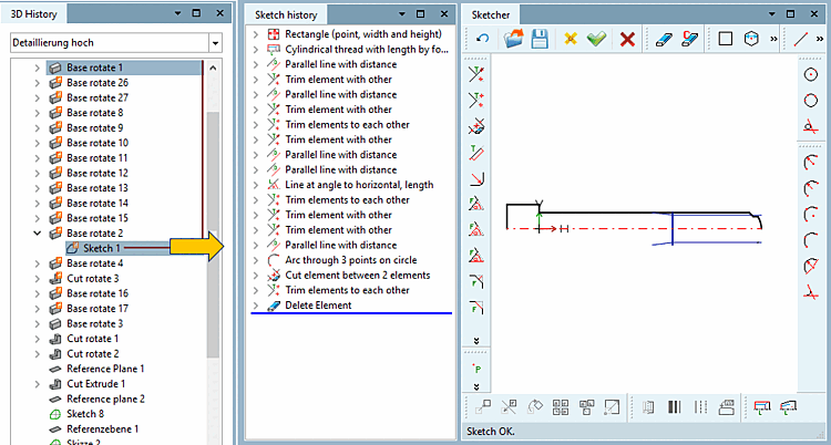
![PARTdesigner with sketch history [Sketch history], sketcher [Sketcher], variable manager [Variable Manager], table [Table] and 3D view](https://webapi.partcommunity.com/service/help/latest/pages/en/3dfindit/doc/resources/img/img_d064ac2ac72a4725b4b00287774b7857.png)
PARTdesigner with sketch history [Sketch history], sketcher [Sketcher], variable manager [Variable Manager], table [Table] and 3D view
You can delete these as in PARTdataManager and move them to another monitor if necessary.
![[Note]](https://webapi.partcommunity.com/service/help/latest/pages/en/3dfindit/doc/images/note.png) | Note |
|---|---|
The two illustrations above show the default view once with 3D history [3D History] and once with sketch history [Sketch history] and Sketcher.
| |
![Standard toolbar [Default]](https://webapi.partcommunity.com/service/help/latest/pages/en/3dfindit/doc/resources/img/img_c3dca4cb1caa48f58d285540b6d34bb2.png)
![View menu [View]](https://webapi.partcommunity.com/service/help/latest/pages/en/3dfindit/doc/resources/img/img_292e0cfe1e8644b3b29158c4609a001a.png)
In the following you will get a short overview on the single docking windows (working areas) with a link to the respective chapter:
The 3D History docking window is a central "showplace" within the PARTdesigner. Its context menus are used to call up the Sketcher (with Sketch History [Sketch history] ) and create the component.
All design steps are documented in the sketch history [Sketch history] so that the respective component structure can be traced and possibly modified at a later date. When a new file is opened, the feature tree only displays the three basic levels XY, ZX, YZ. All further design steps (sketches , rotations, extrusions, etc.) are added to these levels.
The button
 button or the corresponding menu item opens the 3D History docking window or brings it to the foreground.
Detailed information on the 3D history [3D History] can be found at Section 7.6, “ Docking window "3D History " ”.
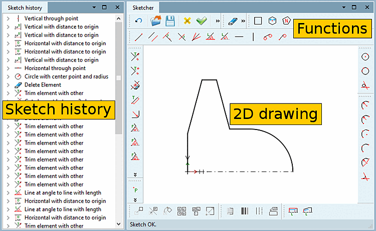
A 3D solid must always be created using a 2D sketch. This 2D sketch is created in the Sketcher dialog area.
The drawings are created here in individual design steps, which in turn form the basis for extrusions and rotations in the 3D history [3D History] dialog area.
The Sketcher button
 button or the corresponding menu item opens the Sketcher and Sketch History [Sketch history] docking windows or brings them to the foreground.
Detailed information on the Sketcher can be found at Section 7.9, “ Docking window "Sketcher " ”.
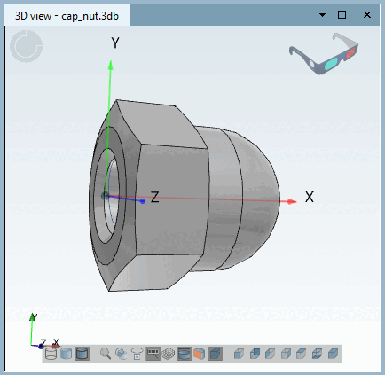
The 3D window button
 button or the corresponding menu item opens the 3D view docking window or brings it to the foreground.
Detailed information on the 3D view can be found at Section 7.7, “ Docking window " 3D view " ”.
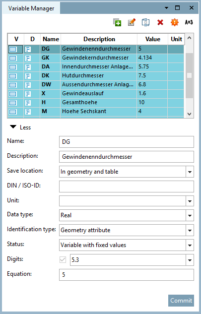
In the PARTdesigner instead of fixed dimension values, variables are set up for which specific values are stored in tables. This method has the advantage that a separate drawing does not have to be created for each component characteristic.
In the Variable manager [Variable Manager] docking window, you can create new variables or change the details of existing variables.
The Variables Manager [Variable Manager] button
 button or the corresponding menu item opens the Variable Manager [Variable Manager] docking window or brings it to the foreground.
Detailed information on the variable manager [Variable Manager] can be found at Section 7.8, “ Docking window " Variable manager" ”.
The Table window button
 button or the corresponding menu item opens the Table docking window or brings it to the foreground.
Changing a table row or a value range automatically visualizes the corresponding characteristic in the 3D view, sketcher [Sketcher] or 2D derivation docking window.
If PARTdesigner is started via the 3db file, the table appears by default in the lower area of PARTdesigner (see Fig. „PARTdesigner with 3D history [3D History], 3D view, variable manager [Variable Manager] and table [Table] “). This view is also used if a prj or 3db file is opened within PARTdesigner file menu [File] -> Open to open a prj or 3db file.
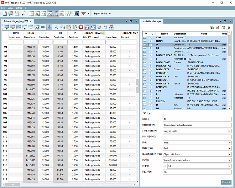
If PARTdesigner is started via the tab/tac file, the table is given a large area by default. This view is also used when a tab/tac file is opened within PARTdesigner file menu [File] -> Open to open a tab/tac file.
Detailed information on the table [Table] can be found at Section 7.12, “ Docking window " Table " ”.
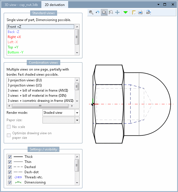
The 2D deriv [2D derivation] ation button
 button or the corresponding menu item opens the 2D deriv [2D derivation] ation docking window or brings it to the foreground.
To display the solid from the 3D view in 2D mode, please select a perspective (Front [Front], Back, Right, Left, Top, Bottom ) or view under Standard views [Default views] or Combination views.
Also see Section 7.10, “ Docking window "2D deriv ation" ”.
Details on the 2D view in the PARTdataManager can be found under Section 7.10.1, “ Create 2D derivation ”.