 |
Analyse assemblies --- Document scan + Purchineering
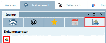
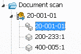
In PARTdataManager under Part selection -> Structure select the tabbed page Document scan.
With the Document scan you can achieve two things:
Check the up-to-dateness of PARTsolutions parts of an assembly loaded in the CAD system
Analyse, which parts of an assembly are own parts and which are PARTsolutions parts
Applying of Purchineering Analysis Functions on the result structure (optionally plus manually added further parts)
The import is carried out within a wizard.
During the scan process the assembly parts are automatically sorted in the following sections:
This makes sense, because after the Document scan various purchineering analyses can be applied to the different groups. Make or Buy for example at own parts, Supplier search at standard and supplier parts.
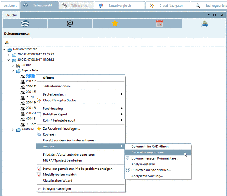
In order for the purchineering analyses to be able to be applied to the Document scan, the geometries have to be imported.
The respective option Import geometry is displayed in the Import document structure dialog box.
When an import has been processed without geometries, they can be imported afterwards.
For this purpose now you can find the context menu command
 at the respective parts (Icon Import geometry. (Multiple
selection with Ctrl key)
at the respective parts (Icon Import geometry. (Multiple
selection with Ctrl key)After a successful import and generation of the fingerprints the icons change.
Use Native Checkin for geometry import
When using OSDM or CATIA it is probably better not to use NativeCheckin at the geometry import. In this case only empty tables without attributes are created. If desired deactivate the checkbox.
The procedure step by step as a whole
The assembly to be scanned is opened in the CAD system.
In general assemblies of any size can be scanned. But please regard, that scanning of complex assemblies can be time consuming.[108]
Start the scan either in PARTdataManager under tabbed page Part selection -> Structure -> tabbed page Document scan by clicking on
 Start document scan
or from CAD system by clicking on Start analyse.
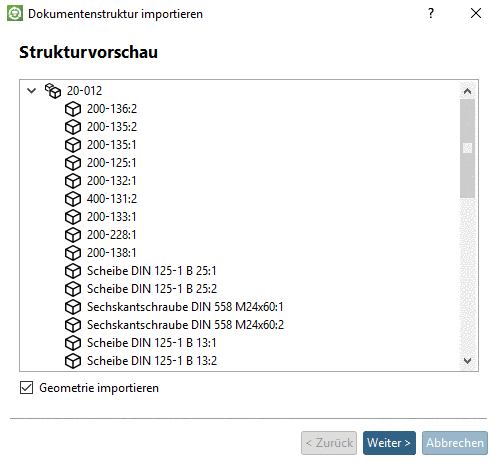
In the Import document structure dialog box the section Structure preview opens and the document structure of the assembly loaded in the CAD system is displayed.
You can perform the import of the document structure with or without geometry:
In the Import document structure dialog box the section Classify parts is displayed.
Pre-classify parts (optional):
Enable the checkbox in order to activate input options.
Purchased parts expression (recognize supplier parts)
If for example the property "Supplier" is available in the CAD system, then you can reference to it in the input field Purchased parts expression.
Enter the following expression for example in Fortran syntax. Notes concerning Fortran syntax are found under Section 6.1.1, “Fortran Syntax ” in PARTsolutions - Administration Manual.
Supplier .NE. ''
This means, if the field "Supplier" is not empty, then the respective part is classified as supplier part.
Recognize the following standards (recognize standard parts)
If certain terms like DIN, EN, ISO, etc. are part of the document name, then the part is classified as standard part.
Some options are already listed with checkbox. Under Custom you can insert any further terms (comma separated).
Result of the classification process
The classification process sorts the parts into the following classes:
Perform purchineering analyses
Now you can perform purchineering analyses for any directory or project. Detailed information on this is found under Section 3.1.13.1, “ Purchineering ”.
At the My parts folder perform Make-or-Buy Report for example or at the Supplier parts folder perform Find suppliers for example.
Check for up-to-dateness at PARTsolutions parts
During the check for up-to-dateness the assembled 3D parts are compared with the current catalog state.
Icons for up-to-dateness of PARTsolutions parts


When a scan is not needed anymore, then simply delete it with the context menu command Delete document scan.
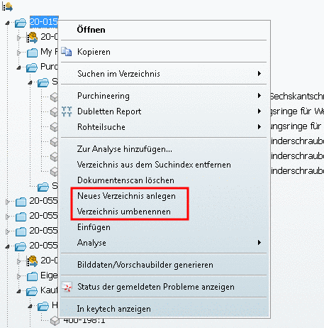
Create directories and move content:
In order to create the desired structure at the Document scan tabbed page, you have the following commands and methods available:
Before performing analyses like Make or Buy, for example on the base of the document scan, you can fill the newly created directories, so that further parts are included in the analyses.
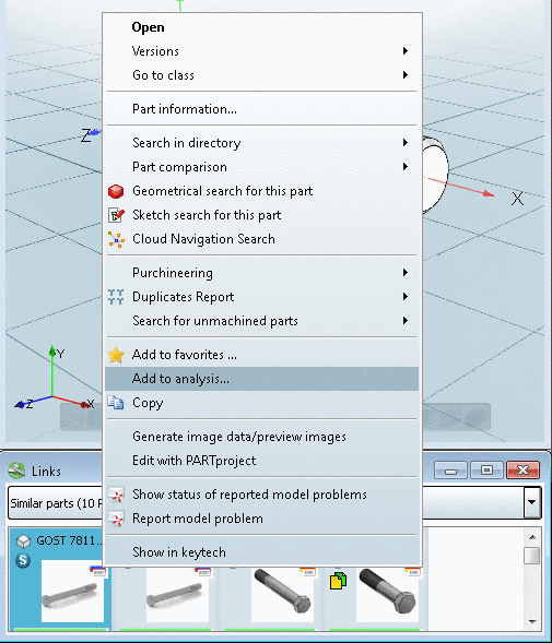
You can find the command Add to analysis... at several places in the context menu:
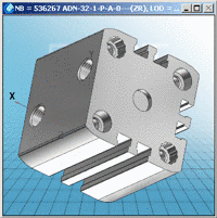
The following figure exemplifies how you can enhance the directory structure in order to include further parts in the analyses, in addition to the scanned assembly.
You can move complete scans, directories and single parts (multiple selection with Ctrl key) into newly created directories via Drag & Drop.
![[Note]](https://webapi.partcommunity.com/service/help/latest/pages/en/3dfindit/doc/images/note.png)
Communicate cross-departmental via comment function:
In the context menu of each directory or project, under Analysis you can find the command Document scan comments....[109]
-> The dialog box Document scan comments opens. Insert your comment and confirm with .
-> In the
respective directory or project line the comment icon is displayed
 . When you move the mouse over the icon, the comment
is displayed in a tooltip.
. When you move the mouse over the icon, the comment
is displayed in a tooltip.
By clicking on
the comment icon the dialog box Document scan comments opens again. You can
insert any further comments. When you delete the content (e.g. via
selection, ),
the comment icon disappears again.
Open scan documents in the CAD system
Via context menu command Analysis -> Open document in CAD, open the scan documents in the CAD again.[110]
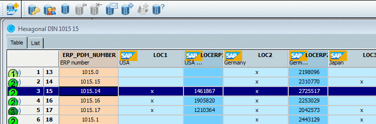
Document scan with ERP integration / Show status icon
ERP line information is also overtaken and displayed in the document scan.
At characteristics with a price higher 100 (in the following figure 110) a pink icon is displayed.
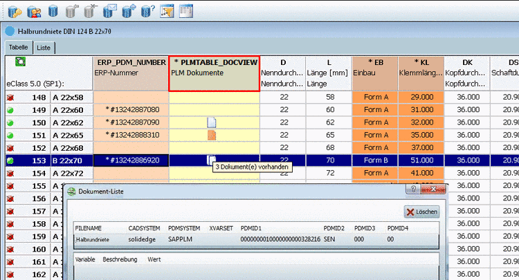
If this part is used in an assembly and scanned by the document scan, then it will be displayed there as well.

