
This class describes planar, rectangular surfaces for which certain restrictions apply when placing or setting up the device (e.g. drilling holes).
Analogous to the other two-dimensional CP classifications, the local, 2-dimensional coordinate system is given by the connection point (see Section 5.12.11.9.2, “Definition of outlines / contours”). In particular, the X and Y axes define the orientation of the blocked surface in space.
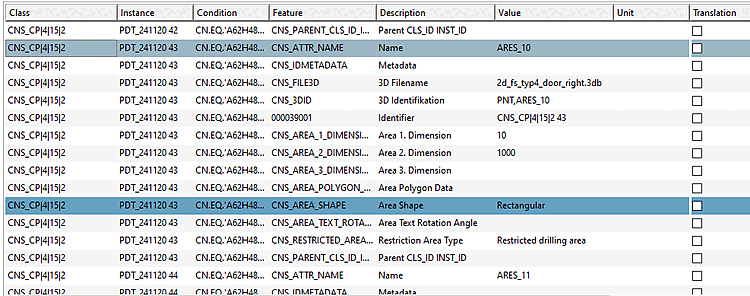
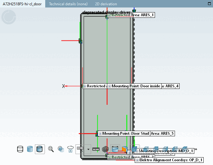
Classification of a rectangular drill stop surface with a width of 10 mm and a height of 1000 mm. Note the geometry is determined analogously to Section 5.12.11.9.2, “Definition of outlines / contours”.
In general, the shape of the area is defined in the same way as in the previous chapters. In this case, the "Restriction Area Type" attribute allows the following values:
| Enumerated value | Meaning |
| Restricted Placing Area | No placement on this surface |
| Restricted Drilling Area | Drill blocking surface |
| Restricted routing range | No wiring via this region |
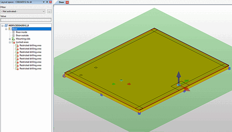
This class can be used to predefine properties of models that are highly customizable, especially in the enclosure area. The following illustration shows an EPLAN export of a door with 5 blocking areas (5 x drill blocking area). This is necessary because drilling holes in these areas would destroy either the rubber seal or the door lock.
A door with a rubber seal is a typical application of barrier surfaces.
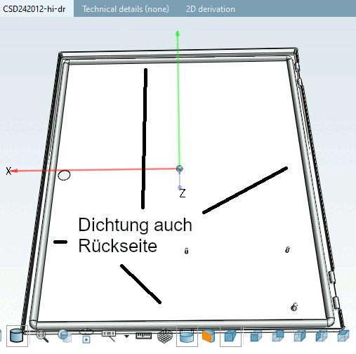
Blocking surfaces in EPLAN: The bordered shape of the blocking surfaces results from the fact that the rubber seal on the back must not be destroyed.