
In the case that your geometry has a connection point for ...
... that needs to be transferred to Revit, please proceed as described below and publish the eCATALOG 3Dfindit Connection point as one of the points mentioned here.
![[Note]](https://webapi.partcommunity.com/service/help/latest/pages/en/installation/doc/images/note.png)
Open the 3db file and set the required connection point which can freely be named.
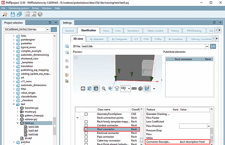
Select the Classification tab page and then the 3D view subpage.
Open the Select connection point [Choose connection point] dialog via the context menu of the 3D view.
Activate the Duct connector class under Revit classification.
Enter a description text under Connector Description.
![[Tip]](https://webapi.partcommunity.com/service/help/latest/pages/en/installation/doc/images/tip.png)
Connection points can be created anywhere in eCATALOG3Dfindit. Functional connection points (suitable for Revit) must be created in the center of a planar surface (center of gravity), for example the center of a circle or the intersection of all angular tangents (see https://en.wikipe dia.org/wiki/Centroid).
It is recommended to create an extrusion at the position where the connector should be placed. (>1.4 mm diameter / extrusion length).
If it is not possible to have a plane surface in the 3db available, the CADENAS Revit interface will attempt to create a “dummy solid” (2x2x2 millimeter) at the position where the connector should be created. This should not be the preferred way to design a model, as the end result in Revit will not be 100% identical with the eCATALOG model.