
Check part [Test part]
 checks the integrity of the part to ensure error-free export to the various CAD systems.
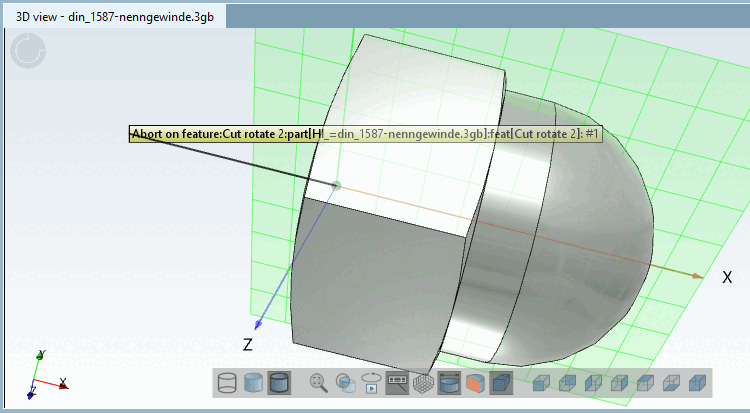
If, in the course of the test run, problems arise, this is directly documented in the 3D view of the part (see figure).
![[Note]](https://webapi.partcommunity.com/service/help/latest/pages/en/partsolutions_user/doc/images/note.png)
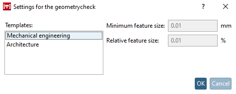
Click on Check part [Test part].
-> The Settings [Settings for the geometry check] for geometry check dialog box opens.
Be sure to select the appropriate template. This is used to set the minimum feature size [Minimum feature size] and relative feature size [Relative feature size].
Mechanical engineering parts [Mechanical engineering], for example, must not be tested with the Construction [Architecture] setting. BIM parts, on the other hand, must be tested with construction [Architecture], so that export problems to Revit are avoided, for example, because elements are < 1.4 mm.
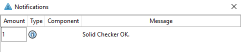
-> A corresponding message appears in the Notifications docking window.
See also Section 7.9.8, “Problem avoidance ”.