Published elements are used on standard parts, for example, to make it easier for users to place parts exported from PARTsolutions in their CAD system. For parts with published elements, intelligent insertion methods are then automatically PARTsolutions Placement dialog automatically offers intelligent insertion methods.
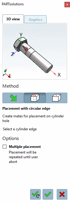
In order for a fastener e.g. to be placed in a hole it needs a defined orientation in the coordinate system.
The existing insertion points are used for this, as they already have a complete coordinate system.
A plane and an axis (with direction) have to be defined.
The Z axis of the connection point determines the axis, X and Y axes determine the plane.
The implementation is carried out using published elements [Published elements], for which the current CNS class system must be installed.
For setting published elements proceed as follows:
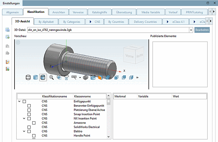
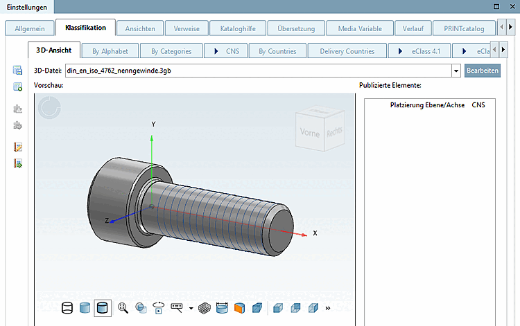
Select in PARTproject the 3db file of the part.
To set the published elements, use the preview area in PARTproject which appears if you have selected a 3db file under Project selection on the left.
Right-click in the 3D area and select Select [Choose connection point] connection point.
-> The same-named dialog is opened.
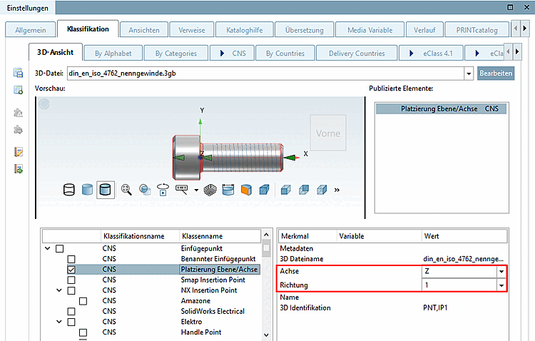
Select the name of the connection point that you want to publish and confirm with .
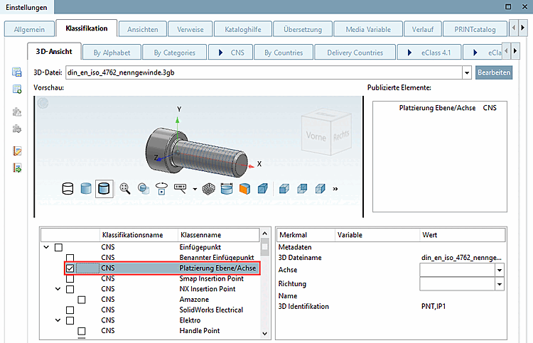
-> The dialog area for selecting the class name [Class name] and characteristic [Feature] opens.
Activate the checkbox for Placement plane/axis.
Optionally, make an entry under Name. However, this is not currently used.
In order to clearly orient the published element set the following 2 parameters:
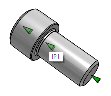
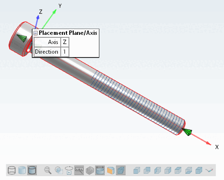
Axis identifies the axis of the connection point to be used for the positioning. If the green pyramid points vertically to the bearing face it is the Z axis.
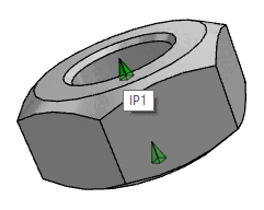
There are two values possible:
1: The part is inserted in positive direction of the Z axis (e.g. in bolts).
0: The part is inserted in negative direction of the Z axis (e.g. in nuts).
Presentation in PARTdataManager
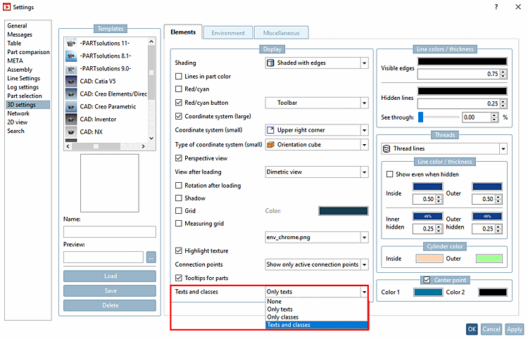
Specify whether you want to display published elements [Published elements] in the PARTdataManager display.
Make the appropriate default setting under PARTdataManager -> Extras -> Settings [Preferences] -> 3D settings -> Elements -> Display -> Texts and classes.
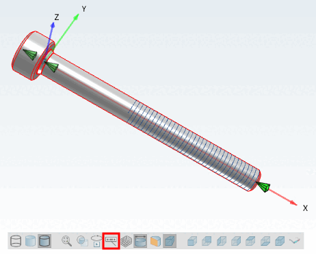
You can switch the display on and off at any time using the Show texts and classes toolbar button.
![[Note]](https://webapi.partcommunity.com/service/help/latest/pages/en/partsolutions_user/doc/images/note.png)
![Select connection point - [Choose connection point] Call](https://webapi.partcommunity.com/service/help/latest/pages/en/partsolutions_user/doc/resources/img/img_c7ff831415ad4a7abe75cfb34e8899f9.png)
![Select connection point [Choose connection point] - dialog](https://webapi.partcommunity.com/service/help/latest/pages/en/partsolutions_user/doc/resources/img/img_480b79e338f04edb9d811cfcb3ef8d97.png)