
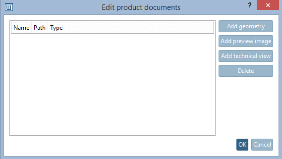
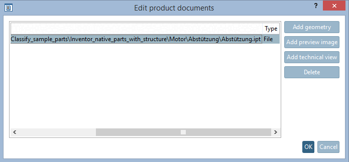
On the Edit product documents [Edit documents in product] dialog page, you can add geometries, preview images and technical drawings.
Complete process using the example of adding geometry [Add geometry]:
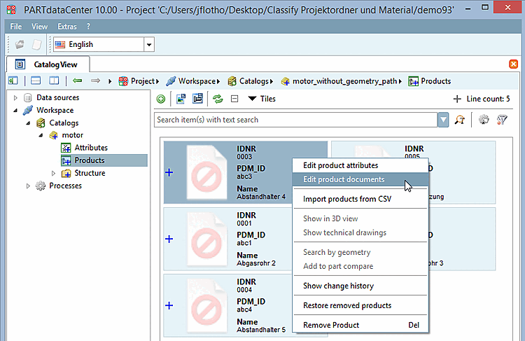
Select a product line and click on the context menu command Edit product documents [Edit documents in product].
-> The same-named dialog box opens.
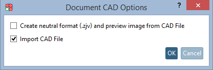
-> The Document CAD Options [Document CAD options] dialog box opens.
Activate the Import CAD file [Import CAD File] option and click .
-> The document is entered in the Edit product documents [Edit documents in product] dialog.
Then click on the button in the product view
 Create geometry and preview image from CAD file [Create geometry and preview from CAD Data].
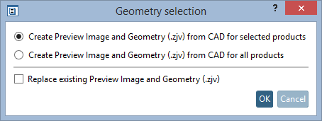
-> The Geometry selection dialog box opens.
Select the appropriate option (in this example, the preview image and geometry (.zjv) should only be generated for the selected product) and confirm by clicking .
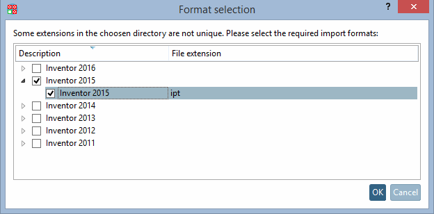
-> The Format selection dialog box opens.
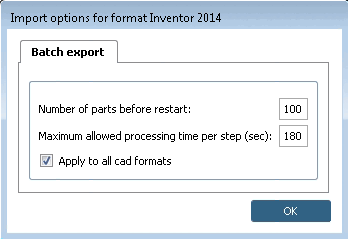
The dialog box for batch export options opens.
As a rule, you can leave the default settings as they are. Confirm by clicking on .
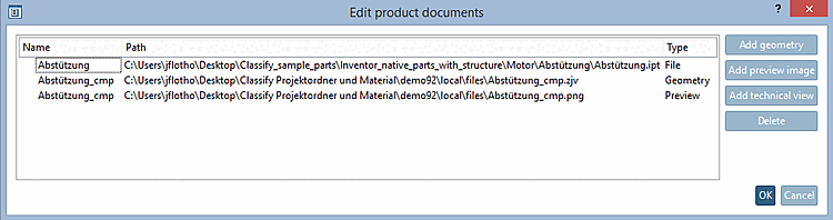
-> In the Edit product documents [Edit documents in product] dialog box, you will see the following files:
![[Note]](https://webapi.partcommunity.com/service/help/latest/pages/en/partsolutions_user/doc/images/note.png)
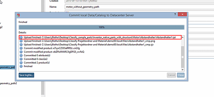
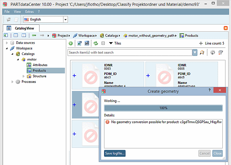
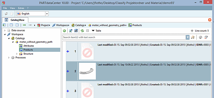
You can recognize the successfully passed through process at the displayed preview image.
The process is similar for Add technical drawing [Add technical view] and Add preview image.
When importing technical previews to a whole class (prj) or a single dataset, you can also use Multipage TIFF and SVG.
The call is made in PARTdataCenter via context menu command Edit product documents [Edit documents in product] -> Add technical drawing [Add technical view].
![Edit product documents [Edit documents in product] -> Add technical drawing [Add technical view]](https://webapi.partcommunity.com/service/help/latest/pages/en/partsolutions_user/doc/resources/img/img_f38b85acc4a341b4b1988db9e6a44556.png)
However, this requires the installation of ImageMagick, which is used to convert the added files into PNG format.
To convert SVG, please set the following block in $(Cadenas_user)/partdatacenter.cfg and adjust the path to ImageMagick according to your installation.
[conversion:svg]
program=C:\Program Files\ImageMagick-7.0.10-Q16-HDRI\magick.exe %path% %targetpath%
format=png
(%targetpath% is a placeholder for the temporary file which is then created by the code.)