
Parts should preferably be modeled with rule-based bodies and kept as simple as possible (cylinder = extrusion of a circle instead of rotation of a rectangular). For special cases (e.g., sweeps) it may be necessary to rotate a non-rectangular shaped sketch. This is geometrically allowed for high detail level (LOG) but generates more computational operations for the CAD file creation and results in a higher possible error rate when creating the geometry in CAD. In particular, see Section 3.5.3, “Regular Bodies for VDI Models” and Section 3.5.2.3, “LOG (formerly called "LOD")”.
The global alignment of the objects (direction of the X/Y/Z axes) must be set to match the orientation of the target systems.
![[Note]](https://webapi.partcommunity.com/service/help/latest/pages/en/partwarehouse/doc/images/note.png) | Note |
|---|---|
It is also highly recommended to avoid many rotations within parts (and assemblies) as these rotations create more operations in the CAD interfaces. | |
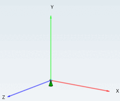
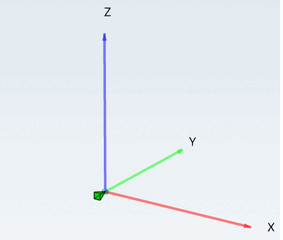
The alignment for MEP objects is explicitly described in VDI 3805 (more details can be found at Section 3.5.2.6, “Sample objects”.)
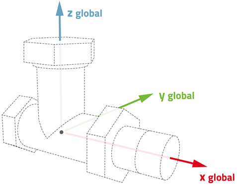
For pipe fittings / pipe accessories, the prescribed modeling guidelines of VDI 3805 in the associated sheets are also binding.
Every domain (in VDI 3805 grouped in sheets) of MEP parts has its own orientation. Pumps, valves and others have different positions of the absolute zero point.
![[Important]](https://webapi.partcommunity.com/service/help/latest/pages/en/partwarehouse/doc/images/important.png)
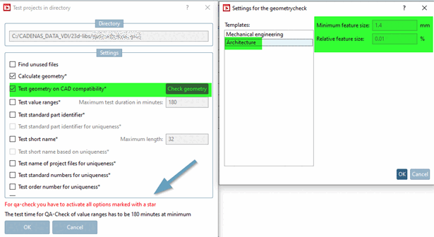
This is the basic requirement for a "TestMeta" (geometry and variant check at project and directory level) to achieve QA level >4. See the eCATALOG 3Dfindit manual in the section Section 5.8.2.1.16, “ Test project / Test directory ” Test Section 5.8.2.1.16, “ Test project / Test directory ”
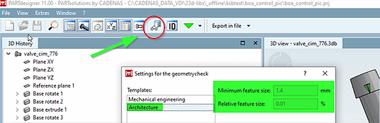
Sketches with a simple structure, referenced and parameterized on levels and the immediate checking of the generated geometry with the PARTdesigner Geometry checker ( Check part [Test part] function) in the correct setting is the elementary basis for an easy-to-read data structure that can be maintained in a short space of time.