General information about the company and partnerships
Don´t miss anything! Inform yourself aboutall news and events.
The next dimension visual 3d search engine for manufacturer components
Fast and comfortable support for all questions about our products & solutions.
Download 3D CAD Modelswith 3Dfindit for free
Use our contact form or find a branch office nearby.
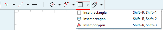
Section 7.9.3.6.1, “ Insert rectangle ”
Section 7.9.3.6.3, “ Insert hexagon ”
Section 7.9.3.6.4, “ Insert N-corner ”