
- 7.9.3.1. Basic information on operation
- 7.9.3.2. Default
- 7.9.3.3. Delete
- 7.9.3.4. Shapes -> Points
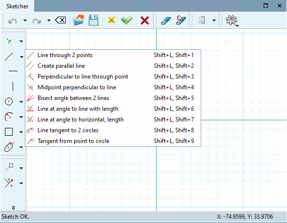
- 7.9.3.5. Shapes -> Lines
- 7.9.3.6. Forms -> Special
- 7.9.3.7. Shapes -> Circles
- 7.9.3.7.1. Circle with center point and radius/point
- 7.9.3.7.2. Circle through 3 points
- 7.9.3.7.3. Circle through center point and tangential element
- 7.9.3.7.4. Create circle tangent to 2 elements (circle/line/arc)
- 7.9.3.7.5. Circle tangential to 3 elements (circle/line/arc)
- 7.9.3.7.6. Circle tangent to 3 circles
- 7.9.3.7.7. Insert slotted hole
- 7.9.3.8. Shapes -> Arcs
- 7.9.3.9. Shapes -> Ellipses and ellipse segments
- 7.9.3.10. Attributes
- 7.9.3.11. Modify -> Transform
- 7.9.3.12. Modify -> Crop (Part 1)
- 7.9.3.13. Modify -> Crop (part 2)
- 7.9.3.14. Modify -> Thread
- 7.9.3.15. Tools in drawing mode
As of V12 tools are displayed in groups by default.
Clicking with the secondary mouse key at any place in a toolbar will open a menu to turn on and off the toolbars:
The following illustration shows the toolbar names and also the group names as they are used when the Group tools setting option is deactivated.
![Display of functions with setting option "Group tools [Group tools] " activated](https://webapi.partcommunity.com/service/help/latest/pages/en/3dfindit/doc/resources/img/img_8258d7d5a0cb47bcbd99d41dd0babc53.png)
The Group tools function is switched on by default. You can find the option to switch it on and off in the PARTdesigner under Tools [Extras] menu -> Settings [Preferences...]... -> Sketcher (hist.) [Sketcher (feat.)].
The following figure shows the toolbars with names without grouping:
![Display of functions with setting option "Group tools [Group tools] " deactivated](https://webapi.partcommunity.com/service/help/latest/pages/en/3dfindit/doc/resources/img/img_85ef69d59cbd4fbd99be5f5f4efe8605.png)