7.9.3.4.1. Connection points
for assembly construction
7.9.3.4.1.1. Connection points in general
|  |
| Prev | Next |
The parts created in the PARTdesigner can be configured [Configurator] with the configurator[101] to assemblies. To do this, the parts must already have PARTdesigner precisely defined and named connection and insertion points must be assigned to the parts.
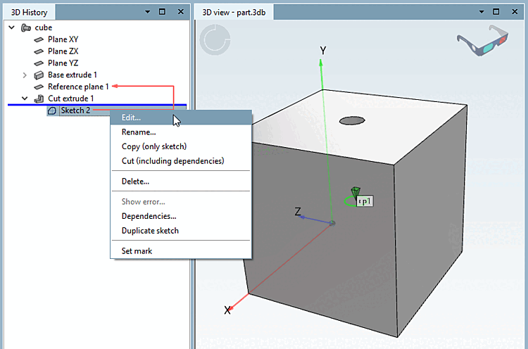
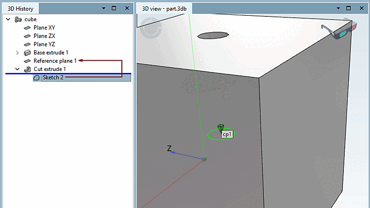
A cuboid contains a boring into which a screw is to be inserted later (assembly configuration). Therefore a connection point needs to be applied for the boring.
Click on the area [Face] in which the hole is located. --> The corresponding sketch [Sketch] appears in the history [History] with a colored background.
Right-click on the context menu of the sketch (in this example, Sketch 2).
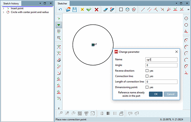
"Catch" the center of the circle (boring) with your cursor and affix it with a simple mouse-click.
--> The point gets a green triangle symbol .
--> The Change parameters [Change parameter] window opens.
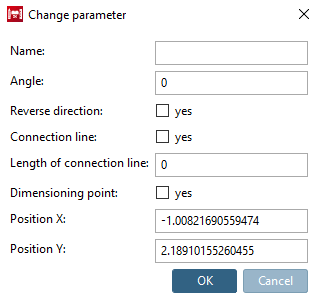
If you place the connection point freely (without "snap"), the options Position X and Position Y are also available in the dialog.
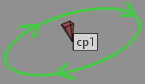
Specify a name for the connection point - e.g. cp1 - and confirm with .
Optionally, you may make changes in the other fields as well.
Angle: Rotation of the connection point
![[Note]](https://webapi.partcommunity.com/service/help/latest/pages/en/3dfindit/doc/images/note.png)
Note The connection point is rotated around the tip of the pyramid. You can find an example of this at Section 7.13.5.7.3.1, “Starting Position on Rotation”.
If you require rotations in other layers, please work with an appropriately set reference layer on which you place the connection point.
You can find another use case at Section 7.9.3.4.1.4, “ Connection points on miters ”.
Reverse direction [Reverse direction]: Reversing the direction is required for a hinge, for example. The hinges should fit together in opposite directions.
Insertion line [Connection line] and length of the insertion line [Length of connection line]: Insertion lines can be used for movable elements. For example, for connectors of profiles that move in a groove. See Section 5.18.1.4, “ Create insertion line ”.
Dimension point [Dimensioning point]: Activate this option if a connection point should also be used as a dimension point. See Section 7.16, “ Docking window "Dimensions " ”.
Click on the button Accept changes
 .
.--> The sketcher [Sketcher] is closed.
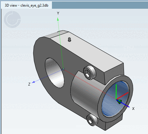
--> In the 3D view, the connection point is also indicated by a three-dimensional green triangle symbol .

By default, the coordinate system is not shown at connection points.
However, you can it enable by setting the key value to "1" (under $CADENAS_USER).
[Settings3DPane]
cpCoordinateSystem=1