
- 7.16.1. Example: Create dimensioning
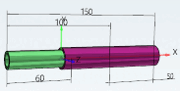
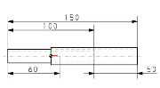
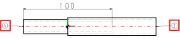
- 7.16.2. Horizontal, vertical and parallel dimensioning
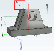
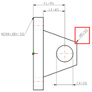
- 7.16.3. Radial dimensioning
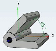
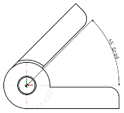
- 7.16.4. Angular dimensioning
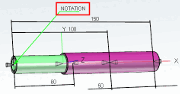
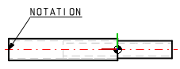
- 7.16.5. Annotation
- 7.16.6. PART-ANNOTATION
- 7.16.7. Optional parameters Details
- 7.16.8. 3D Parameter
- 7.16.9. Using variables
- 7.16.10. PARTdesigner Expressions
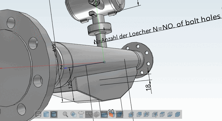
Create dimensions (notations) for 3D view and 2D derivation
In PARTdesigner, dimensions [Dimensionings] can be created parametrically in a separate docking window during the modeling process. Individual dimensions can also be set editable so that the end user can click on them and select alternative component variants. (See Section 7.16.7, “ Optional parameters Details ” -> Variable mapping ).
In 3Dfindit/PARTdataManager, in the part selection [Part selection], these dimensions are then automatically generated for the 3D view and 2D derivation. When exporting, the 2D derivation is transferred to the CAD system.
| Horizontal, vertical and parallel dimensioning | Radial dimensions | Angular dimensions | Annotations / Position numbers for list of material |
|
|
|
|
|
|
|
|
|
|
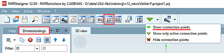
If the Dimensions [Dimensionings] docking window is not displayed, call it up using the toolbar icon
 icon.
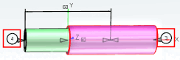
icon.Make sure that the connection points are displayed in the 3D view.
If necessary, click on the Show connection points button in the standard toolbar.
At first set the required connection points (if not yet available)
Since the measuring points reference to dimensioning points/connection points, they must either already be available within the part or specifically set.
The connection points [Connection points] (displayed in green in individual parts, displayed in gray in assemblies) can be used in the same way as pure dimension points (displayed in blue).
It is essential to note on which surface/plane the dimension points are set!
If dimension points are not set correctly, the dimensioning in the 3D view with the Perspective projection setting option looks as if it is pointing to the wrong points.
The dimensioning points should be moved to the nearest position in direction of viewer.
File for saving the dimensioning parameters
If a file for managing the dimensions does not yet exist, a file with the same name as the project
*.dimis automatically created in the project and the key CUSTOMDIMENSIONSV9 in the assembly configuration project file (*asmcfg.prj), assembly template project file (*asmsbl.prj) or individual part project file (*.prj) points to this*.dim.If a file
customdimensions.txtstill exists from older versions, it will continue to be used and existing data will be read from there.
Do not use translations for automatic dimensioning! [113] Instead, use a value range variable with naming [Value range variable with naming] with neutral text.
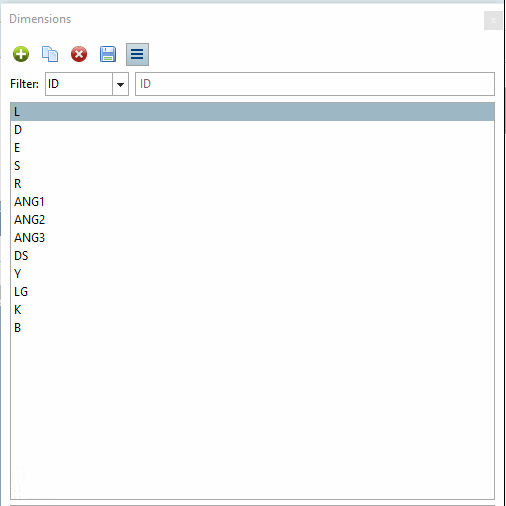
Workspace is the Dimensions [Dimensionings] docking window. It is divided into two dialog areas:
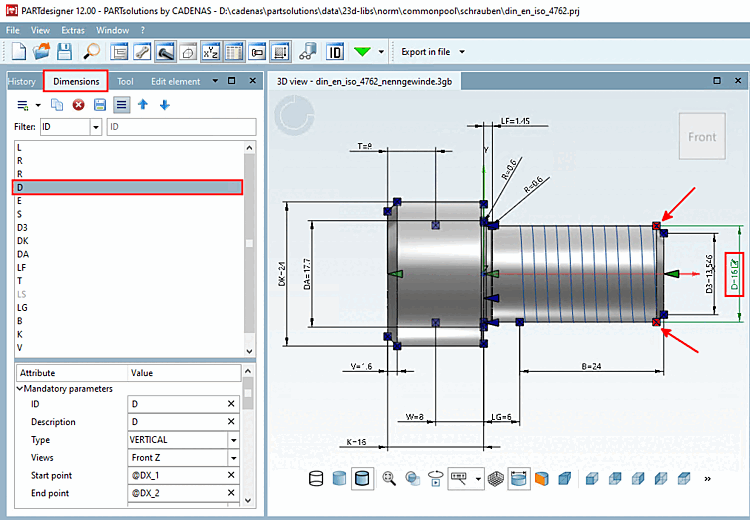
In the upper dialog area, all dimensionings are listed with their description (ideally identical to the variable name such as L, R, D, etc.), in the lower area, the particular parameters of the selected dimensioning.
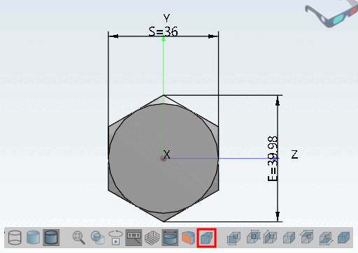
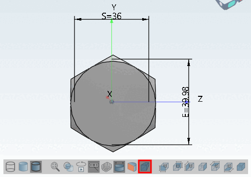
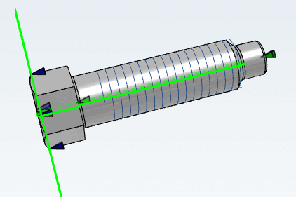
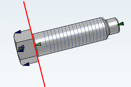
When you select a dimensioning, the corresponding dimensioning is highlighted in green in the 3D view and the starting point [Start point] and end point [End point] of the dimensioning are highlighted in red. Conversely, clicking on a dimensioning in the 3D view [3D view] highlights the corresponding line on the right.
As soon as all mandatory parameters [Mandatory parameters] have been set, the dimensioning is immediately displayed in the 3D view.
As soon as all mandatory parameters [Mandatory parameters] are set, the dimensions are also immediately visible in the 2D derivation.
If you click on a dimensioning line, all the parameters of the dimensioning are listed in the lower dialog area, separated into mandatory parameters [Mandatory parameters], optional parameters [Optional parameters] and 3D parameters [3D Parameter]. These can be created here or simply changed again. Changes are immediately visible in the 3D view (provided the mandatory parameters are available).
You can find detailed information on the mandatory parameters in the single chapters of the dimensioning types. Detailed information on the optional parameters can be found in an own chapter Section 7.16.7, “ Optional parameters Details ”.
Value changes are marked, once on the parameter itself by an undo icon
 (click on the icon to undo the change) and in the list of dimensions in bold red.
The undo icon is displayed as long as no changes [Save changes] have been saved using the Save changes
 icon has been saved. Undo is no longer possible after this.
Above the listing of dimensionings the following buttons are shown:
-> A new dimension is immediately added to the list of dimensions. The HORIZONTAL type [Type] appears automatically. Adjust the selection in the list field under Type if necessary. You can change the type [Type] at any time.
–> A copy of the dimensioning selected in the list is created.
-> The selected dimensioning is removed from the list. Only when Save changes
has been clicked, the deletion is complete and there is no "Back".-> Changes are saved in the file
*.dim.As long as changes [Save changes] have not yet been saved using the Save changes
button, an icon is displayed at the top of the ID line and next to each parameter that has been changed is displayed at the top of the ID line and next to each changed parameter, which you can use to undo the relevant action.


[113] A feature algorithm [Attribute algorithm] such as "VARIABLEX=TRANSLATE(VARIABLE) should NOT be used here.