A small example will be used to show how to create a new dimensioning.
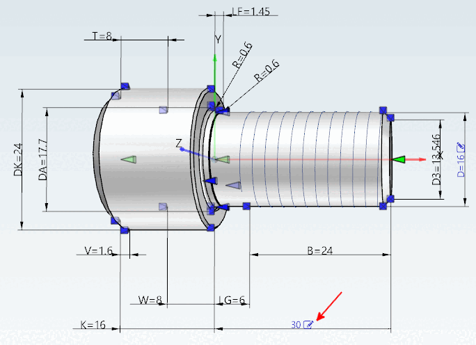
A horizontal dimensioning shall be created for the length of a bolt:
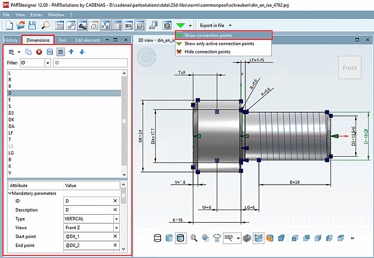
Open the Dimensions [Dimensionings] docking window using the Toolbar icon
 . You can drag and drop it as a
separate window.
. You can drag and drop it as a
separate window.-> The dimension points (blue) and connection points (green in individual parts, gray in assemblies) are now displayed.
Make sure that the dimensions are displayed in the 3D view.
If necessary, click on the Show dimensions [Show Dimensionings] button in the 3D view toolbar.
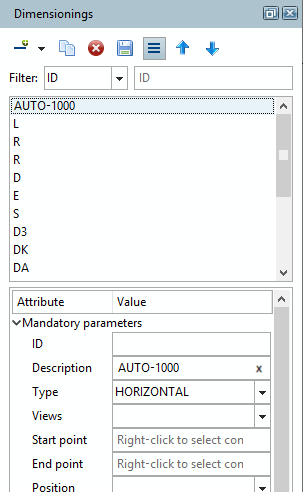
Click on the Add new dimensioning [Create new dimension] button
 .
.-> An "AUTO" dimension line appears in the upper dialog area and the type [Type] HORIZONTAL is created by default under Mandatory parameters. (Correct here in the example. Otherwise, adjust the selection in the list box)
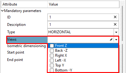
Under Mandatory parameters -> Views, select the desired 2D views on which the dimensioning is to be displayed. Here in the example Front+ Z.
Views that contain a dimensioning can be recognized in the 3D toolbar by a corresponding icon with a dimensioning line
 .
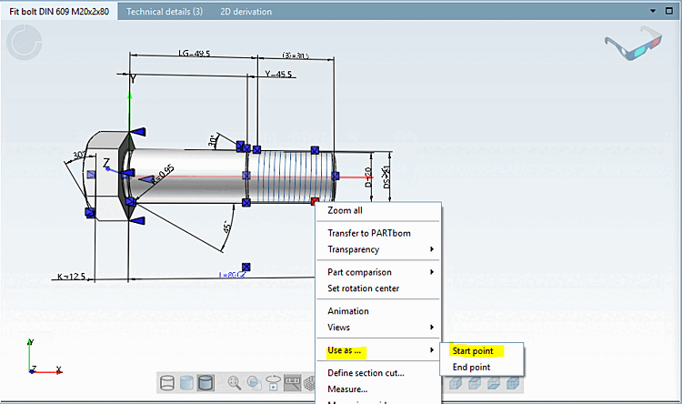
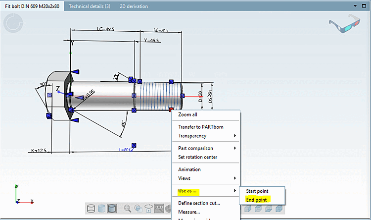
.Now determine the starting point [Start point] of the dimensioning.
Select the desired connection point [Connection point].
-> The connection point [Connection point] is highlighted in red.
Call up the context menu and select Use as. [Use as ...].. -> Start point.
Proceed in the same way for the end point [End point].
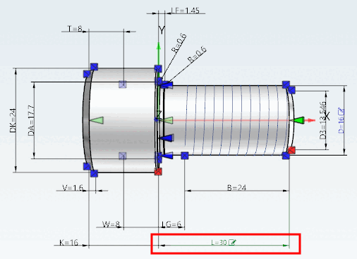
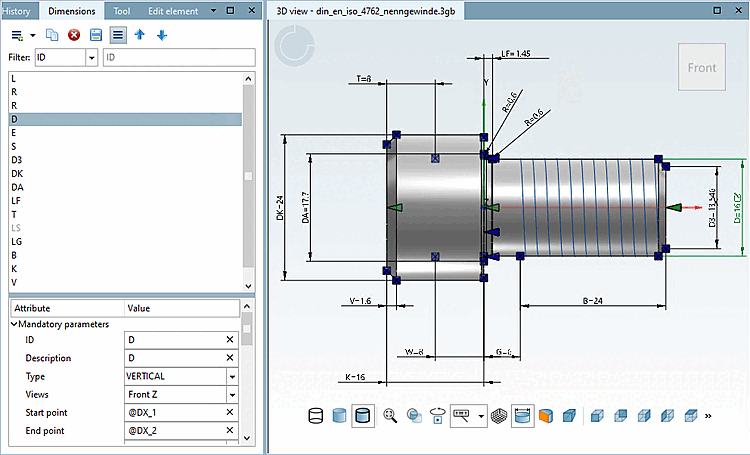
Select the value BBOX (Bounding box) in the Position list field and the value -DIST*12 (here in the example) as the distance dimension (BBOX) [Offset (BBOX)].
-> As soon as all mandatory parameters [Mandatory parameters] are set, the dimensioning appears in the 3D view.
You can now modify (e.g. text) or set (e.g. arrow size [Arrow size] ) optional parameters [Optional parameters] as required.
You can find a complete overview of PARTdesigner expressions under Section 10.1, “PARTdesigner-Expressions ”.
Once the variable name is entered, the editing icon
 is displayed.
The user can later change the characteristic to be exported here. Compare Section 2.1.7.6.6, “Change characteristic via dimension labels ” in PARTsolutions - User
Adjust the value for font size accordingly (here in the example "DIST").
Set the arrow size [Arrow size] and arrow factor [Arrow factor].
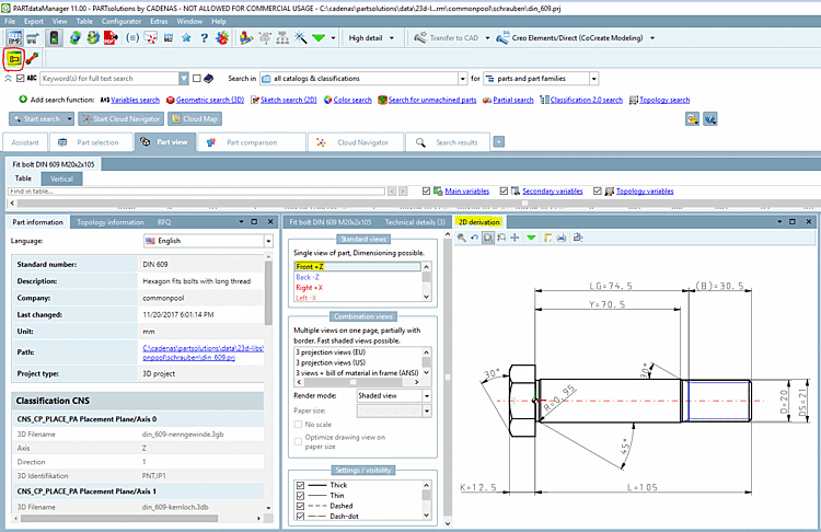
The set dimensioning is also used for 2D derivation.
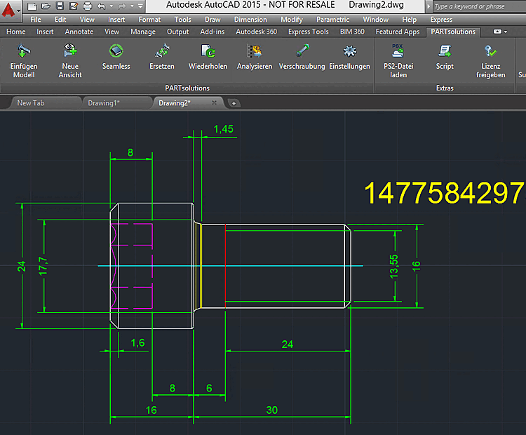
When exporting to the CAD system the dimensioning is transferred as well.

![[Tip]](https://webapi.partcommunity.com/service/help/latest/pages/en/3dfindit/doc/images/tip.png)