7.9.3.4.1. Connection points
for assembly construction
7.9.3.4.1.2. Naming convention for connection points and insertion lines
|  |
| Prev | Next |
The naming convention will be illustrated using a profile as an example:
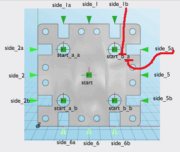
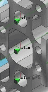
One connection point is required in the center of the profile cross-section and one in each hole. Compare Fig. „3 connection points at the beginning and end, 8 insertion lines at the channels“.
The connection point in the center of the profile cross-section is called start, the others are enumerated with start_a, start_b etc.
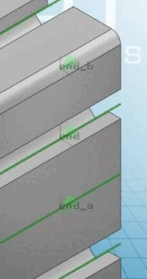
Exactly the same applies to the end of the profile.
Lateral connection points (insertion line)
![[Note]](https://webapi.partcommunity.com/service/help/latest/pages/en/3dfindit/doc/images/note.png) | Note |
|---|---|
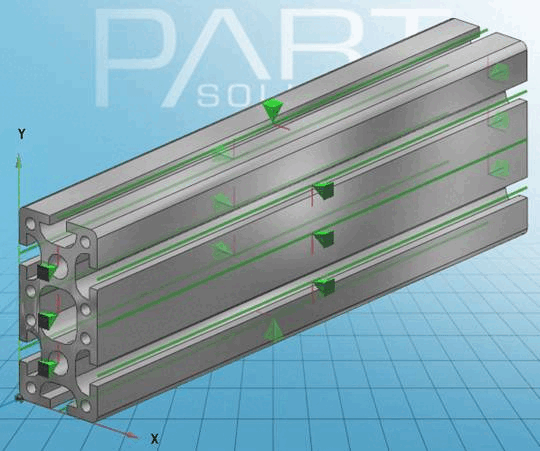
The lateral connection points [Connection points] are created as an insertion line [Connection line]. See Section 5.18.1.4, “ Create insertion line ”.
| |
![Insertion line [Connection line] Insertion line](https://webapi.partcommunity.com/service/help/latest/pages/en/3dfindit/doc/resources/img/img_f8fd15d41967446fa90a8bfb609f3964.png)
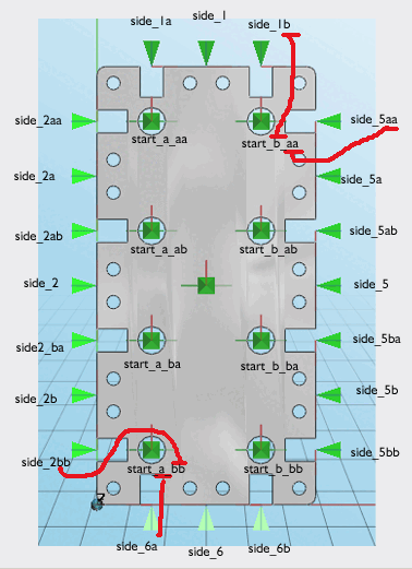
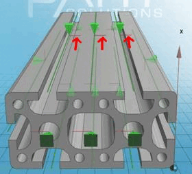
The following illustration shows an example of the naming convention for the side insertion lines. Their base sketch is on the start level of the profile.
![[Important]](https://webapi.partcommunity.com/service/help/latest/pages/en/3dfindit/doc/images/important.png)


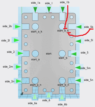
Example of a complex naming convention with many connection points and insertion lines and different proportions
The start/end connection points/insertion lines are now a letter combination of top/side or bottom/side: