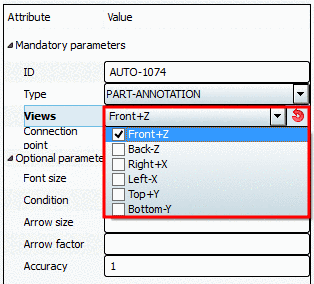
Each part-notation must contain the following parameters:
ID is only required, if a dimensioning serves as Base dimension for a chain dimensioning.
The description is shown in the above listing. Initially a description is automatically given, when creating a new dimensioning, which can be adjusted as desired.
When creating a new dimensioning HORIZONTAL is automatically displayed. Adjust selection in the list field to PART-ANNOTATION. You can change the type anytime.
At the desired 2D views, where the dimensioning shall be displayed, activate the checkbox.
The respective position number is placed close to the desired connection point.


![[Note]](https://webapi.partcommunity.com/service/help/latest/pages/en/ecatalogsolutions/doc/images/note.png)

