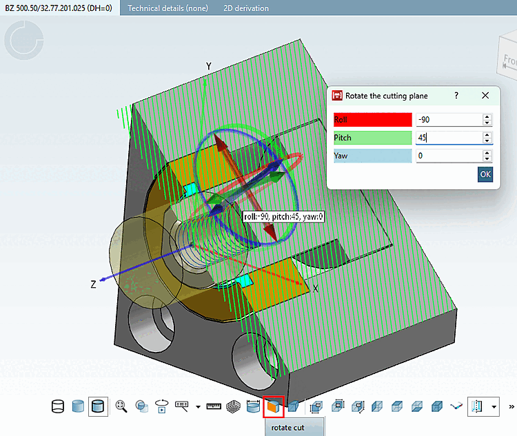
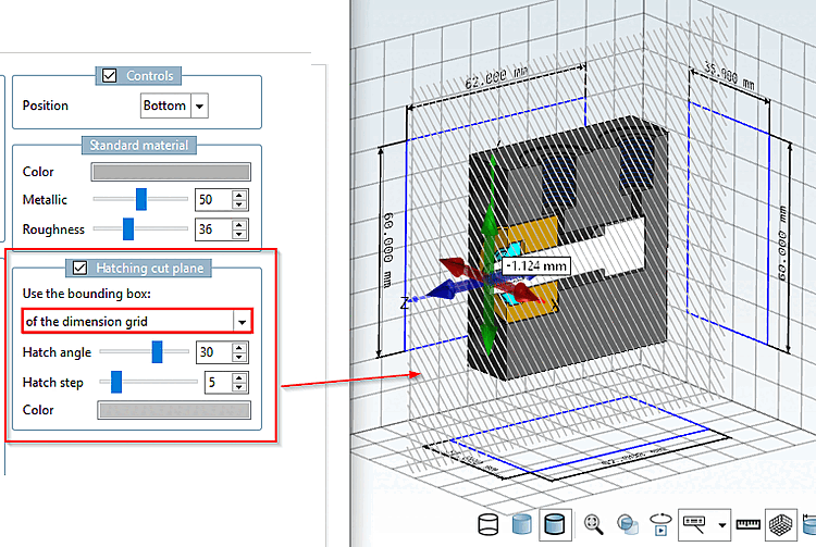
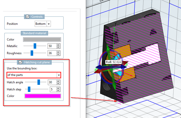
The cut plane can optionally be displayed with hatching. In the settings dialog, you can make the appropriate adjustments.
![PARTdesigner > Tools [Extras] Menu > Preferences... [Settings...] > 3D Settings [3D settings] > Hatching Cut Plane [Hatching cut plane]](https://webapi.partcommunity.com/service/help/latest/pages/en/ecatalogsolutions/doc/resources/img/img_4169d712c8ca436d9b660bfecddfe016.png)
PARTdesigner > Tools [Extras] Menu > Preferences... [Settings...] > 3D Settings [3D settings] > Hatching Cut Plane [Hatching cut plane]
Hatch Style Layer [Hatching cut plane]: Enabled / Disabled
Click
Click the corresponding button in the toolbar
 or alternatively click the Define Section Plane... [Define section cut...] command in the context menu of the
3D window.
or alternatively click the Define Section Plane... [Define section cut...] command in the context menu of the
3D window.
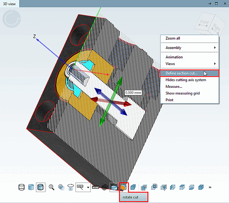
After the command is issued, a navigation crosshair with the main axes is displayed.
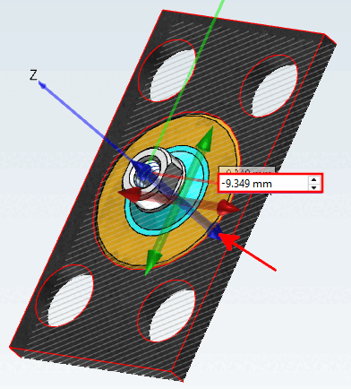
Select the cutting plane by clicking on the corresponding arrow.
Move the cutting plane by holding down the mouse button and dragging an arrow, or by entering a value in the input field, or by using the small black arrow buttons next to the input field.
After clicking the " Rotate Section [rotate cut] " button, rotation circlesare also displayed on the navigation crosshairs. Select the desired circle and rotate the section by holding down the mouse button. Clicking on the values opens the rotation dialog, where you can enter values to precisely specify the rotation.