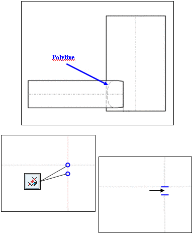
Polylines, such as for example occur when cutting two cylinders, are also split into "calculable" single segments with this function (circular arcs, ellipses, etc.).
As a group of single segments, the polyline can be edited and/or trimmed as well as imported to a CAD system with the "recognizable" properties.
In below example (section highly zoomed in) the Polyline can, for example, be taken and cut via Cut element between 2 elements.
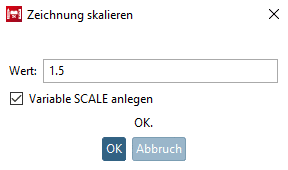
After clicking on the icon Scale drawing the same-named dialog box is opened.
In the input field Value, enter the desired Scale factor.
Optionally, activate Create variable SCALE.
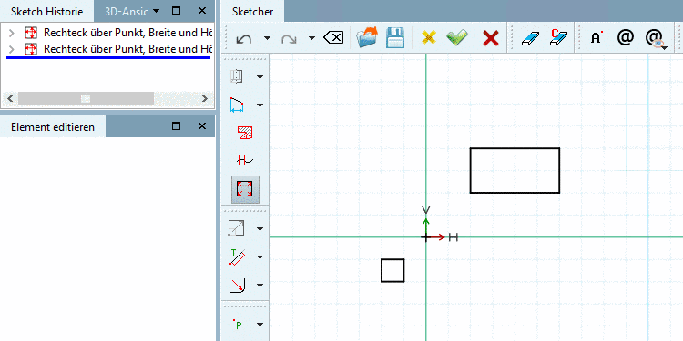
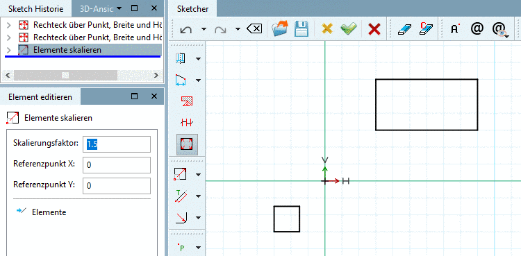
-> The drawing is scaled and the docking window Edit element is opened.
In the docking window Edit element, you can adjust the Scale factor and Reference point X / Reference point Y.


![[Note]](https://webapi.partcommunity.com/service/help/latest/pages/en/ecatalogsolutions/doc/images/note.png)


