5.12.11.9. Classification according to CAX basis 5.12.11.9.2. Definition of outlines / contours |  |
| Prev | Next |
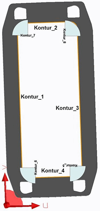
Various classifications, e.g . Drilling patterns CNS_CP|4|2, describe planar (2D) line strings in 3D space that are suspended from a connection point. The 2D coordinate system of this geometry is defined by the X or Y axis of the connection point.
![The connection point defines a local coordinate system in 3D space; X-axis [red], Y-axis [green], Z-axis [blue].](https://webapi.partcommunity.com/service/help/latest/pages/en/ecatalogsolutions/doc/resources/img/img_6c950a0b71d54b95a70885e1e1f02c8e.png)
The connection point defines a local coordinate system in 3D space; X-axis [red], Y-axis [green], Z-axis [blue].
The normal of this surface is given by the Z-axis of the connection point. In the CAX area, contours such as drilling patterns, mounting cut-outs or mounting grids are often required.
In principle, there are two ways of modeling this in the CNS system:
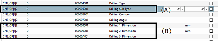
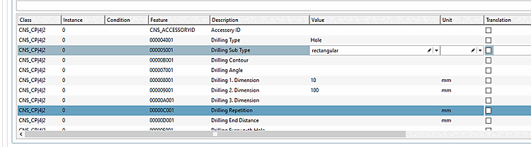
The parametric description contains two elements, the geometric shape as an enumerated value (Drilling Sub Type ) and a series of parameters that instantiate this shape. The system allows up to 3 parameters (Drilling 1st Dimension, Drilling 2nd Dimension, Drilling 3rd Dimension ), the meaning of which depends on the selected shape:
| Drilling Sub Type | Drilling 1st dimension | Drilling 2nd dimension | Drilling 3rd dimension |
| round | Radius | - | - |
| quadratic | Length | - | - |
| rectangular | Width | Height | - |
| slotted hole | Radius | Length | - |
| hexagon | Outer radius | - | - |
| ... | ... | ... | ... |
This scheme is used for a wide variety of classes, such as the mounting cut-outs and the component system description of cabinets, as well as the labeling area.
![[Note]](https://webapi.partcommunity.com/service/help/latest/pages/en/ecatalogsolutions/doc/images/note.png) | Note |
|---|---|
The number of supported geometries varies in each case. In general, only circles (round), rectangles (rectangular) and squares (quadratic) are recommended. | |
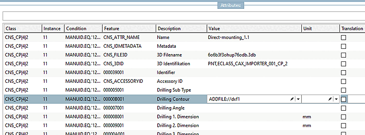
The second option for providing geometries is made possible by external vector graphics (DXF files), which were added to the project in PARTproject under Additional export formats.
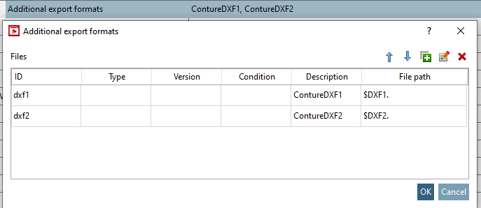
Project with 2 additional files. The file identifiers are given by dxf1 and dxf2. These identifiers enable the link between external files and the classification system.
The classification refers to the external files via the Drilling Contour attribute, whereby the syntax is given by ADDFILE://<value of ID>.
In general, the DXF file should be limited to lines and circular arcs. This restriction results from the properties of automated NC milling machines.