

Relationship between two translations/rotations
By using "Add Additional Rule [Add an additional rule relationship]," you can link multiple movements so that certain components— such as the two gripper jaws of a gripper—move not sequentially, but in sync.
This feature enables complex, formula-based motion dependencies between translations and rotations in assemblies and, in particular, significantly improves the visualization and simulation of moving assemblies.
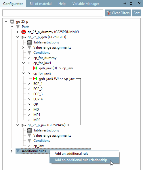
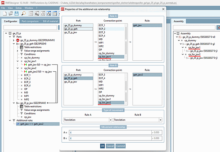
In an assembly configuration in PARTdesigner, add an additional rule relationship between two rules so that the motion of Rule A is linked to the motion of Rule B.
To do this, right-click the " Additional Rules [Additional rules] " entry and then click " Add Additional Rule Relationship." . [Add an additional rule relationship]
-> The "Properties [Properties of the additional rule relationship] " dialog box for the additional rule relationship [Properties of the additional rule relationship] opens.
Specify the desired rule [Rule] under Rule A by selecting the component [Part] and attachment point [Connection point].
Select the desired rule [Rule] under Rule B by selecting the component [Part] and attachment point [Connection point].
For Rule A [Rule A] and Rule B, select " Translation" or [Translation] " Rotation" from the list box under "Motion Type [Type of movement]."
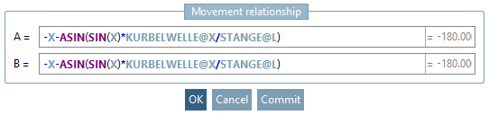
Determine the formulas for A and B under " Ratio of Movement [Movement relationship]," which are to be related to each other.
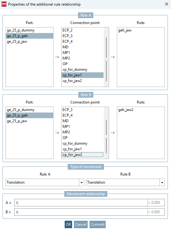
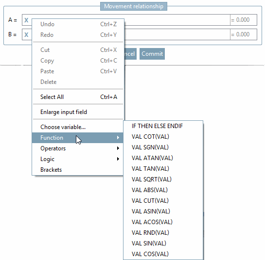
In the simplest case, the relationship between A and B is expressed by two "X"s.
The formulas for Rule A and Rule B must be inverse functions of each other (that is, for example, "X/2" for A and "X*2" for B).
X is the free translation or rotation value of the other rule. This means:
Whether these functions are actually inverse functions is checked using testmeta.
About testmeta also checks whether the values fall within the minimum and maximum limits defined for the rules.
Important: Currently, only the formula for B = ... needs to be specified, since the function currently operates only in the direction in which the assembly is being built up. Movements must therefore be defined from rule A to rule B. To calculate B, the value of A is required (this is available in the formula as X ).
In the formulas, variables from the entire assembly can be used as usual in the format VARIABLE@PART .
Only a subset of the available mathematical functions can be used in the formulas, for example: SIN(X), COS(X), ABS(X), etc.
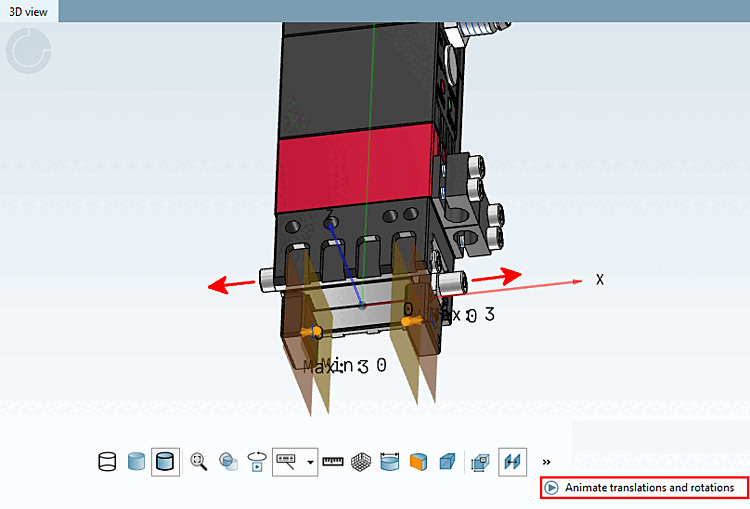
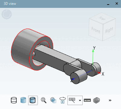
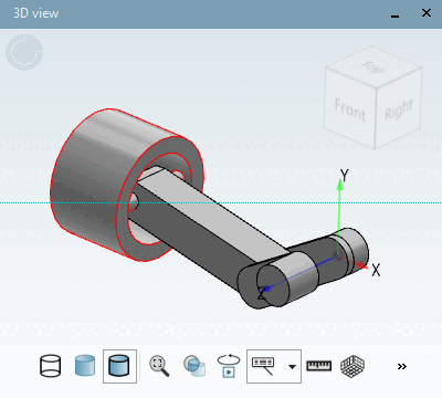
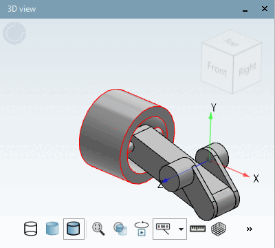
To display the animation (currently only possible in PARTdesigner ), click the "Animate Translations and Rotations [Animate translations and rotations]" button in the 3D view. Previously, all translations and rotations of the rules were displayed one after the other. Now, movements that are linked to each other via additional rule relationships are executed simultaneously and animated together .
Using appropriate formulas, even complex movements—such as those between a piston and a rod—can be modeled.
The relationships currently only work in the order in which the assembly was built. Currently, the formula for moving from Rule A to Rule B must be defined.
If both rotation and translation are to be possible simultaneously within a rule (e.g., for a screw), you can define the relationship between these two types of motion using a self-reference.
To do this, create an additional rule relationship in which Rule A and Rule B are identical.
The motion type for Rule A and Rule B must be set to different values (e.g., rotation and translation).
The formula then defines the relationship between these two types of motion.