
Up to now, the function definitions have been used implicitly using the ECLASS function symbols (IEC 81346 - https://wiki.eclass.eu/wiki/CAx_Funktionssymbole). See Section 5.12.11.5.2, “Connections, IEC function symbols ” In this chapter, we look at the steps required to extend existing data with a fully user-defined function definition in the same way as described in this chapter. This is done without changing existing data.
In order to recapitulate the IEC symbolism introduced in the above chapter, let's take a brief look at the basic structure of the classification. The key point was the introduction of (real/physical) connections CNS_CP|4|3 (Electrical Connection ). The basic functional structure is defined by the Connection EclassSymbolMap attribute and the corresponding connection is classified in this structure. The following illustration describes the current situation using an example with 3 functions, where the first function has one (logical) connection, the second has two (logical) connections and the third has three (logical) connections. To keep the example abstract, the function name is given by SYMBOL1, SYMBOL2, SYMBOL3. The connection names are given by A,B,C,D,E.F.
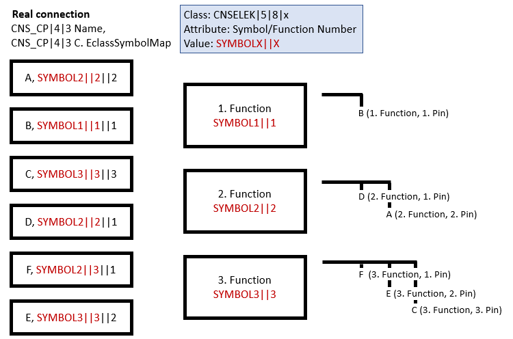
Definition of the functional structure with the help of an example. Real connections are integrated in the functional structure.
The case considered so far concerned function names with a certain "implicit meaning", namely the IEC function symbol given by the name. Often these predefined function definitions are not sufficient or the electrical functionality needs to be specified explicitly. In these cases, the definition of the function structure introduced under Section 5.12.11.5, “Classification of electrical connections (Electrical Connection [CNS_CP|4|3]) ” is retained without restrictions.
The new feature consists of the classes CNSELEK|5|8|1 to CNSELEK|5|8|7, which explicitly specify the electrical function of a node in the function structure. As a consequence, classification can be carried out in exactly the same way as before; in particular, the restrictions in the Connection EclassSymbolMap attribute on IEC function symbols are completely removed.
In essence, an instance of CNSELEK|5|8|x is created for each node in the function structure (i.e. three in the example above). An instance of these function classes therefore describes a series of real connections.
All of these connections should now be specified in more detail by an instance of the function classes; to do this, the corresponding function class instance simply needs to be linked to the corresponding node in the function structure. We achieve the link with this node through the first part of the values of Connection EclassSymbolMap. In the figure above, this is illustrated by the blue box.
Together with the representation described at Section 5.12.11.15, “Symbol representations (Circuit symbols) "Advanced" ”, the scheme presented allows complete flexibility in the machine-readable functional/symbolic description of an electrical part in full analogy to the definition of ECLASS Advanced or EPLAN.
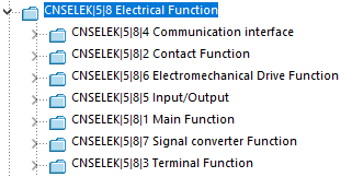
These classes CNSELEK|5|8|x represent the functionality of the ECLASS Advanced Block AAQ676. Cables are an exception, which are modeled differently but equivalently (and mutually convertible) as described above.
CNSELEK|5|8|1 Main function (central function): There may only be one instance of the main function per item. Its exact meaning is very context-dependent. For PLCs[55] the pins for the power supply are usually grouped together under the main function.
CNSELEK|5|8|2 Contact Function (contact function): These functions include pins that belong to contacts and protective circuits, i.e. NO, NC changers and changeover switches, etc.
CNSELEK|5|8|3 Terminal Function (terminal level): These functions combine pins that belong to a terminal (level). In particular, the potential of the terminal level can be defined/modified here if this has not already been done in the ECLASS function symbols.
CNSELEK|5|8|4 Communication interface: These functions summarize pins that enable communication with other parts, especially in PLCs, e.g. the LAN adapter in a programmable logic controller. Among other things, the communication protocol and the type of interface can be defined here (e.g. PROFINET, TCP/IP,...)
CNSELEK|5|8|5 Input/Output (input/output function): This class almost always represents the "PLC pins". Here, for example, it is defined whether the corresponding pins are an analog input/output, digital input/output, the type of measurement and the signal behavior, etc.
CNSELEK|5|8|6 Electromechanical Drive Function (electromechanical drive): This class summarizes pins that belong to electromechanical actuators. A good example are coils that drive the changeover switches in relays, etc.
CNSELEK|5|8|7 Signal converter Function (signal adapter): These classes describe all pins that belong to transformers, rectifiers and other signal adapters, for example.
Within these 7 classes there are attributes which further specify specific functions.
All these classes have 6 attributes in common:
In the case of the terminal function (CNSELEK|5|8|3 Terminal Function ), for example, the potential of all associated connections is defined via the Terminal potential attribute. An important point is that each of these function class instances is responsible for a whole series of connections (CNS_CP|4|3). This mapping between the function and the terminals is described below as an example.
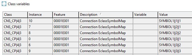
The coupling between the function and all associated pins is achieved via the Symbol/Function Number attribute, which must be filled. The operation of this attribute is explained using the following example. We consider a model with three functions, one with 1 pin, one with 2 pins and one with 3 pins.
| Value of the attribute in Connection EclassSymbolMap (CNS_CP|4|3 ) |
| SYMBOL1||1||1 |
| SYMBOL2||2||1 |
| SYMBOL2||2||2 |
| SYMBOL3||3||1 |
| SYMBOL3||3||2 |
| SYMBOL3||3||3 |
In this case, 3 function classes of CNSELEK|5|8|x must be instantiated. (The following figures show CNSELEK|5|8|3.)
| Attribute | Class instance | Value |
| Symbol/Function Number | 1 | SYMBOL1||1 |
| Function Name | 1 | SYMBOL1 |
| Symbol/Function Number | 2 | SYMBOL2||2 |
| Function Name | 2 | SYMBOL2 |
| Symbol/Function Number | 3 | SYMBOL3||3 |
| Function Name | 3 | SYMBOL3 |
With this scenario, we have enriched a number of pins with a function definition. This allows, for example, the customer-specific adaptation of the predefined IEC function symbols with their own data. The function name in Connection EclassSymbolMap does not have to match the Function Name attribute; Function Name "overwrites" the function name in most target systems. As a rule, however, they should remain the same.
The central point of this construction is the "linking" of a group of pins (belonging to a function) with a new instantiated function class. The attributes of this function class affect all pins belonging to the function.
Link between electrical connection in 3D (CNS_CP|4|3) via attribute "Connection EclassSymbolMap " with the corresponding symbol pin; SYMBOL3||3||3, for example, corresponds to the 3rd pin of the 3rd function of the model, which is given by the identifier SYMBOL3. This represents the previous situation.
The previous use of functions and symbols is shown in the image above. Models that are modeled in this way can be used in this way without restriction. The crucial point is that the properties of the predefined IEC function symbols can be modified or explicitly specified by instantiating the function classes CNSELEK|5|8|1 to CNSELEK|5|8|7.
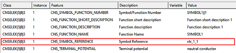
We consider the use case where we want to explicitly influence the potential for a component or a component function. This is shown in the following figure. In addition to the attribute values, which set the short and long description of the function, the potential of the terminal is explicitly set to the neutral conductor via the Terminal potential attribute. The coupling with the situation specified above is set via the Symbol/Function Number attribute with the value SYMBOL1||1.
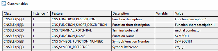
Explicitly instantiated function class analogous to the previous image. The coupling to all connections of a function is carried out via the Symbol/Function Number attribute with the value SYMBOLx||x. Accordingly, the "Terminal potential " attribute sets the potential of all pins (in this case only one) of this function to the neutral conductor.
The core aspect of this exemplary construction is to modify the element of the function structure originally introduced under Connection EclassSymbolMap by the element explicitly defined under CNSELEK|5|8|3. Another important use case is that this construction enables the complete redefinition of own functions that may not yet be described by the IEC standard. In addition, these classes enable the explicit assignment of a user-defined symbol by means of the Symbol Reference attribute (see below).
The classes described above allow the separation between function and symbol in analogy to systems such as ECLASS Advanced and EPLAN. We consider a model that has been correctly classified as described above. In other words, Connection EclassSymbolMap is set correctly in the connections. In addition, these connections are extended by corresponding "function class instances".
In this use case it's very easy to assign a specific symbol to this function (inclusive meta data, meaning the symbol graphic as DXF, 2D pin coordinates within the DXF and other properties). Furthermore there is already a specific symbol catalog within the main catalog path.
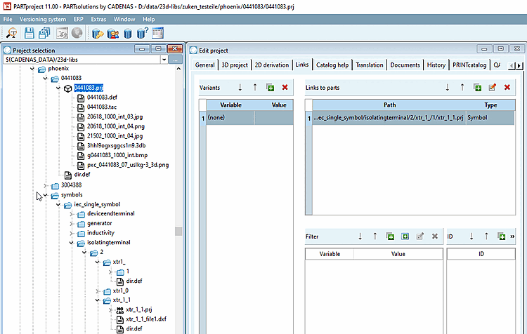
![Typical situation of a catalog that has been enriched by a symbol catalog. The symbol catalog is a catalog with a specific form. The individual project files (NOCAD) only contain classification information and "additional export formats [Additional export formats] " in DXF format. This results in "building blocks" for symbols that can be referenced by the projects in the main catalog as required and also repeatedly.](https://webapi.partcommunity.com/service/help/latest/pages/en/installation/doc/resources/img/img_e531fd9424da41b6ac3c80f5d271fe93.png)
Typical situation of a catalog that has been enriched by a symbol catalog. The symbol catalog is a catalog with a specific form. The individual project files (NOCAD) only contain classification information and "additional export formats [Additional export formats] " in DXF format. This results in "building blocks" for symbols that can be referenced by the projects in the main catalog as required and also repeatedly.
The Symbol Reference attribute enables the integration of a symbol display in the main part or in a specific function of the main part.
For this the following steps have to be processed:
The symbol project from the symbol catalog is embedded in the main part via crosslink.
The symbol from the symbol library is referenced by a (compatible) function of the main part. This is done using the Symbol Reference attribute. Compatible here means that the number of pins of the symbol and function match.
Important for this construction is that both function and symbol contain an "internal structure". Mapping a function with e.g. 3 connections to one with 2 connection will result in an error.
[55] A programmable logic controller (PLC) is a device that is used to control or regulate a machine or system and is programmed on a digital basis. It replaces the "hard-wired" connection-programmed controller in most areas.