
There are 2 main elements: nodes and edges.
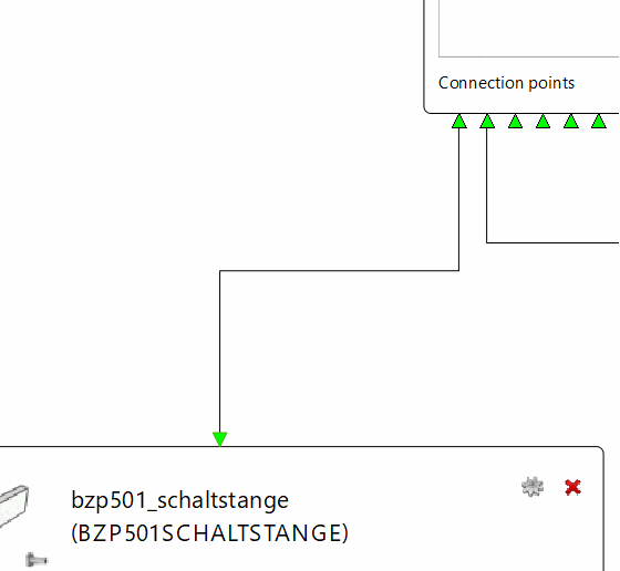
So the assembly is represented as a graph where the nodes are parts and the edges are rules. The connection points are represented as so called ports. You can see the ports in Fig. „Node with Ports“ at the bottom of the nodes.
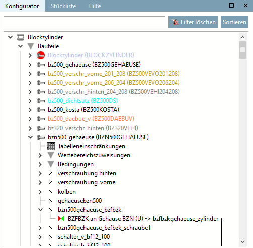
(Compare: In the docking window configurator [Configurator], the assembly with parts, connection points and rules is represented as a tree)
Also in the Graphical Editor, two parts can be connected through two connection points with a rule.
If you open an existing assembly the parts and rules get positioned automatically. If the parts already have a starter-part and rules, the graph can be built. Otherwise the parts get positioned next to each other.
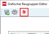
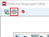
The position of the parts can be freely selected using drag & drop. The rules are not movable and are automatically adjusted to the position of the connected parts. With the Automatically arrange [Arrange automatically] button  button in the toolbar, the nodes can be automatically rearranged.
![Insert part [Add Part]](https://webapi.partcommunity.com/service/help/latest/pages/en/partsolutions_user/doc/resources/img/img_83ae419754d44ac28ff992d4e843029d.png)
Currently, the positions are not saved when closing PARTdesigner are not saved and are automatically repositioned after the assembly is opened
To insert a part, click on the Insert part [Add Part] button button in the toolbar. Once the part and properties have been defined in the Part and Properties dialog, the part is inserted in the editor display area. Via the Properties button
  button in the toolbar opens the corresponding dialog.
In the following figure you can see a part in different shapes corresponding to the current zoom level.
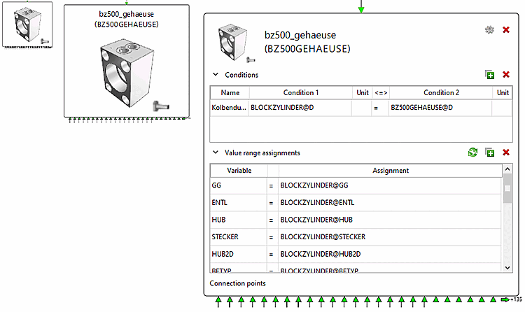
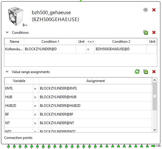
In Fig. „Subassembly“you can see a sub-assembly. In the preview image of the item, you will see a thumbnail that indicates whether it is a part or a subassembly. At the top you can see the name and alias of the item.
Conditions and value range assignments are displayed as tables. You can use the Add condition and Add [Add value range assignment] value range assignment buttons buttons, you can add empty rows to the tables. The values for the Name, Condition
1, Condition
2 and Assignment columns can be entered freely. The values for the columns Article [Item] (sub-assembly only), Unit, <=> and Variable can be selected from a list by right-clicking on the cell. If a row is missing a value or is incorrect, it is highlighted in red. The Delete condition [Remove condition] and Delete value range assignment buttons delete the currently selected row
buttons, you can add empty rows to the tables. The values for the Name, Condition
1, Condition
2 and Assignment columns can be entered freely. The values for the columns Article [Item] (sub-assembly only), Unit, <=> and Variable can be selected from a list by right-clicking on the cell. If a row is missing a value or is incorrect, it is highlighted in red. The Delete condition [Remove condition] and Delete value range assignment buttons delete the currently selected row buttons delete the currently selected row. Value range assignments can be added automatically by clicking the Automatic value range assignments [Automatic value range assignment]
 button. Both tables can be opened with the arrow buttons
 on the left-hand side to close and open them.
The delete component [Delete part] button  at the top right of the article deletes the article - if possible. The same can be achieved by zooming out and right-clicking on a part or sub-assembly and clicking the Delete context menu command. The part properties [Part properties] button
  opens the Properties [Part properties] dialog of the part [Part properties] of the article. If you zoom out, you can achieve the same by right-clicking on a part or sub-assembly and clicking on Properties in the context menu.
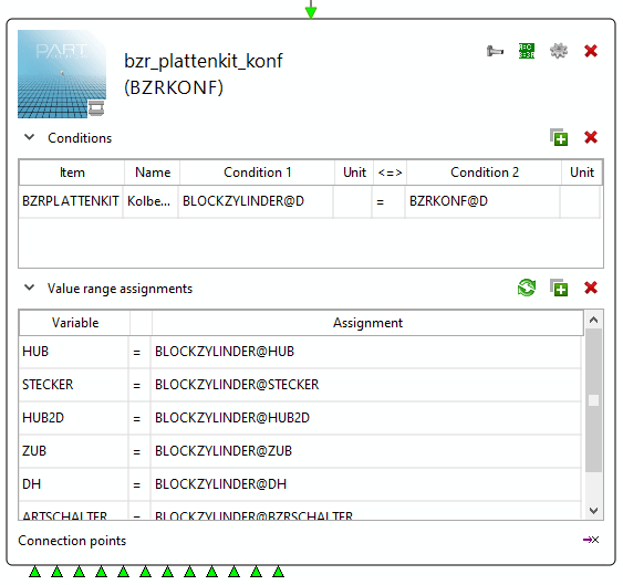
If it is a sub-assembly, there are more buttons. The Release variables [Share variables] button button at the top right opens a dialog for releasing variables from sub-parts to sub-assemblies. The Release connection point [Share connection point] button
  button at the bottom right opens a dialog for releasing connection points of the sub-part to the sub-assembly.
If the part/subassembly is not a starter part it has a dummy connection point at the top of it. This dummy connection point is just for visualizing and not a real connection point.
If you hover over a part/subassembly or select it by clicking on it, all ingoing and outgoing rules are selected too in different colors (see Fig. „Selected Node“).
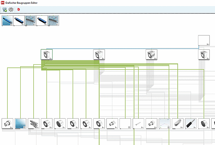
If you double-click on a part/subassembly it will be selected and centered in the editor.
If you right-click on a part/subassembly you can choose ingoing and outgoing rules (if at least one exists). By hovering over the rule or clicking on it the rule will be selected and centered in the editor.