The following explains the basic instructions for use:
Activate button with simple mouse click.
-> The buttons' function is "hanging" on to the cursor and the button is highlighted.
Move the cursor to the desired location in the sketch.
-> Depending on the selected command, the object snap (circular symbol) becomes visible.
Execute the function of the button by simply clicking the mouse at the desired position (e.g. insert line [Insert line] ).
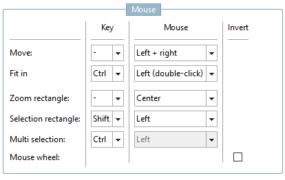
Move: You can move the entire content by holding down the left and right mouse buttons.
Fitting [Fit in]: Double-click while holding down the Ctrl key. -> The entire content of the Sketcher is fitted exactly into the window.
Zoom rectangle: Drag a rectangle while holding down the middle mouse button.
Selection rect [Selection rectangle] angle: Hold down the Shift key and drag a rectangle with the left mouse button.
Multiple selection [Multi selection]: Hold down the Ctrl key and click on the desired elements.
Mouse wheel: Use the mouse wheel [Mouse wheel] to zoom in and out. If you activate Reverse [Invert], it is the other way round. The position of the object changes depending on where you positioned the mouse cursor before rotating.
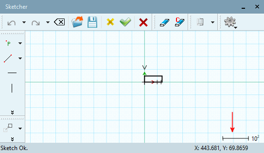
You can see the scaling factor right below. Positive exponential numbers signalize that you zoomed out, negative that you zoomed in. Double-clicking with pressed Ctrl key resets to the standard scaling factor (10 to the power of 0).
You can change the default settings under PARTdesigner -> Extras menu [Extras] -> Settings [Preferences...]... -> Sketcher (hist.) [Sketcher (feat.)] -> Mouse.
Automatic object snap on points and auxiliary points of construction: If you move the cursor in the immediate area of a start, middle, endpoint or intersection point, these points will be surrounded by a small blue circle and thus identified as points and auxiliary points of construction.
You can select any point of construction (yellow point) or auxiliary point of construction (only blue circle) on the element.
Overlapping of two figures lying on top of each other: If two figures lie on top of each other in such a way that two lines lie directly on top of each other, the different lines are selected one after the other. If you have selected the first line with a single left-click, you must move the mouse pointer away briefly. The second line is then selected with another left-click on the line.
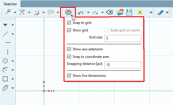
Snap to grid: If, for example, a line is drawn, it is automatically placed on grid lines. Placement between grid lines can only be achieved if the option is switched off.
Grid spacing [Hatch spacing]: Specification in mm
You can set the color for the grid under Color settings.
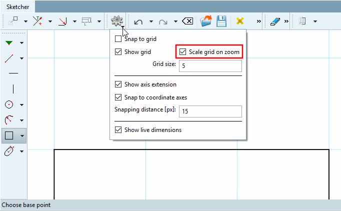
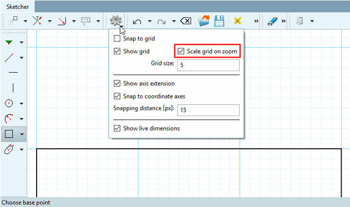
Scale when zooming [Scale grid on zoom]:
If the option is activated, the rasterization is automatically scaled by a factor of 10 when zooming in from a certain point. See the following two illustrations. If the Snap to grid option is activated, this option is automatically deactivated, as snapping to "wrong" points is not desirable.
Scalar parameters: This option is used, for example, when creating circles or drawing angles (e.g. circle through center point and radius/point [Circle with center point and radius/point] or line at an angle a to the horizontal with length L [Line at angle to horizontal, length] ).
For example, if a width of 5 is set, a circle will snap at multiples of 5, regardless in which direction the mouse is moved.
Den Vergrößerungs- / Verkleinerungsmaßstab sehen Sie im Sketcher rechts unten. Positive Exponentialzahlen signalisieren, dass herausgezoomt wurde, negative, dass hereingezommt wurde. Ein Doppelklick mit gehaltener Strg-Taste stellt wieder auf den Normal-Maßstab (10 hoch 0) um.
Display [Show axis extension] axle extension:
Under Color settings, you can set the color for the coordinate system and the axis extension.
Snap to coordinate ax [Snap to coordinate axes] es: If, for example, Snap to grid is switched off but this option is activated, a line is strictly oriented to the coordinate axes, whereby the length remains free in contrast to Snap to grid.
Snap-in distance [Snapping distance] [px]: Default value is 25
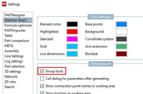
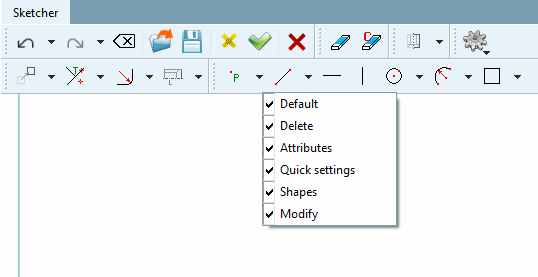
For a better overview, the individual function buttons are grouped together in toolbars with similar functions. In V12, only the last one used is displayed, the others can be accessed via a list box function (small black arrow). In the PARTdesigner under Extras menu -> Settings [Preferences...]... -> Sketcher (hist.) [Sketcher (feat.)] there is the option Group tools, so that you can also return to the old V11 behavior (all buttons are visible).
With the secondary mouse key, click in one of the toolbars and set or remove the checkmark at the desired toolbar.
![[Note]](https://webapi.partcommunity.com/service/help/latest/pages/en/partwarehouse/doc/images/note.png)
Note Most toolbars are visible both in pure sketch mode and in 2D drawing mode (see Section 7.9.2, “Launching the Sketcher ”), some only in 2D drawing mode. You will find a corresponding note in the following list.
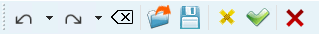
Standard [Default]" toolbar: Pure sketch and 2D drawing mode
"Erase [Delete]" toolbar: pure sketch and 2D drawing mode
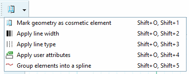
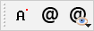
Attributes" toolbar: Pure sketch and 2D drawing mode
Quick settings " toolbar: Pure sketch as well as 2D drawing mode
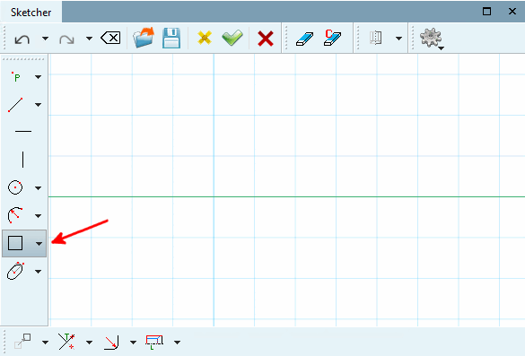
Toolbar " Shapes ": Pure sketch as well as 2D drawing mode
The "Shapes [Shapes] " toolbar contains tools for points [Points], lines [Lines], circles [Circles], arcs [Arcs], N-corners
" Modify " toolbar: Pure sketch and 2D drawing mode
The "Modify [Modify] " toolbar contains tools for transforming [Transform], cropping (part 1), cropping (part 2), thread [Threads]
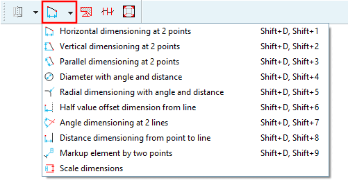
Attributes -> Dimensioning mode " toolbar: 2D drawing mode only
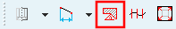
Toolbar " Attributes -> Insert hatching [Insert hatch] ": 2D drawing mode only
Attributes -> Polyline " toolbar: 2D drawing mode only
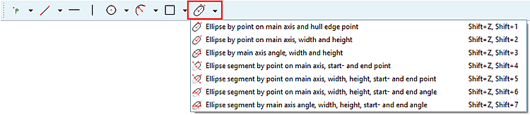
Toolbar " Shapes " -> Tool group "Ellipses [Ellipses] ": 2D drawing mode only
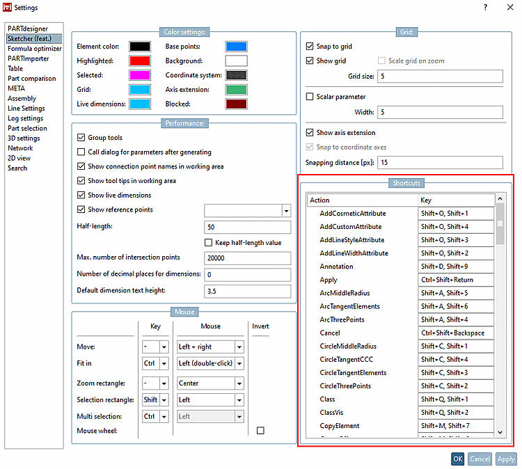
Key commands [Shortcuts] (shortcuts)
You can call up the individual functions in the Sketcher using key commands.
Advantage: time saving. Keyboard shortcuts allow commands to be executed much faster than with the mouse.
Disadvantage: You have to memorize the shortcuts. In addition to the name, the tooltips also show the shortcut so that you internalize them over time.
The following figure shows an overview of all shortcuts.
There are different modes to call them:
Esc cancels the currently selected function.
Under PARTdesigner -> Extras menu [Extras] -> Settings [Settings...]... -> Sketcher (hist.) [Sketcher (feat.)] -> Key commands [Shortcuts] you can customize the existing key commands.
Use Fig. „Overview of key commands [Shortcuts] “ to find the corresponding command. If you know the key combination, you can search for it in the Key column. Enter the new desired key command here and make sure that there is no conflict with an existing one, otherwise the command will not work.
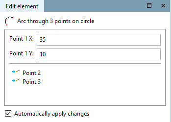
Convert to [Change into formula point] formula point:
If fixed points are used when executing functions, these points appear in the Edit element docking window and not their coordinates. If adjustments are to be made to the coordinates, a point must first be converted into a formula point.
Select the point to be converted.
Arc over 3 points on circumference [Arc through 3 points on circle] -> Convert to formula point [Change into formula point]
Click on the Convert to formula point [Change into formula point] context menu command.
-> The point coordinates are now displayed under Edit element.
Reassign [New allocation of reference point] reference point:
You can also assign other reference points retrospectively (provided they already existed in the sketch history [Sketch history] ).
Click on Reassign reference point [New allocation of reference point] in the context menu.
-> Select new reference or intersection point. [Choose new reference or cut point...].. is displayed in the status bar. is displayed.
-> The function is accordingly adjusted.
Arc over 3 points on circumference [Arc through 3 points on circle] -> reassign reference point [New allocation of reference point]
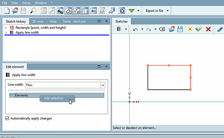
In cases where multiple selection is possible, the item Edit elements [Elements] with context menu command Edit selection is displayed in the Edit element docking window.
![Axle extension [Axis extension] on (default)](https://webapi.partcommunity.com/service/help/latest/pages/en/partwarehouse/doc/resources/img/img_b882370d749349868ba1e80d0b05b87f.png)
![Axle extension [Axis extension] off](https://webapi.partcommunity.com/service/help/latest/pages/en/partwarehouse/doc/resources/img/img_4faa6e40ddd444a28dd8f90cc206ca10.png)

![The "Shapes [Shapes] " toolbar contains tools for points [Points], lines [Lines], circles [Circles], arcs [Arcs], N-corners](https://webapi.partcommunity.com/service/help/latest/pages/en/partwarehouse/doc/resources/img/img_82b634904763408fb9fc3c28c6dd4226.png)
![The "Modify [Modify] " toolbar contains tools for transforming [Transform], cropping (part 1), cropping (part 2), thread [Threads]](https://webapi.partcommunity.com/service/help/latest/pages/en/partwarehouse/doc/resources/img/img_a9530feb82cf4378934b447d18cee0cc.png)
![Overview of key commands [Shortcuts]](https://webapi.partcommunity.com/service/help/latest/pages/en/partwarehouse/doc/resources/img/img_5e666e72873b4e4b8397a641704cc853.png)
![Arc over 3 points on circumference [Arc through 3 points on circle] -> Convert to formula point [Change into formula point]](https://webapi.partcommunity.com/service/help/latest/pages/en/partwarehouse/doc/resources/img/img_f4f6e0e926c4419f8fc20163a1c68783.png)
![Arc over 3 points on circumference [Arc through 3 points on circle] -> reassign reference point [New allocation of reference point]](https://webapi.partcommunity.com/service/help/latest/pages/en/partwarehouse/doc/resources/img/img_bcb7f2d4a2fc407c82bff7a3cc4c0069.png)