3.6.3.1. Rotative
and linear simulation (MCD) 3.6.3.1.1. Example
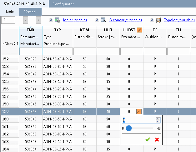
for a linear simulation with a FESTO ADN compact cylinder |  |
| Prev | Next |
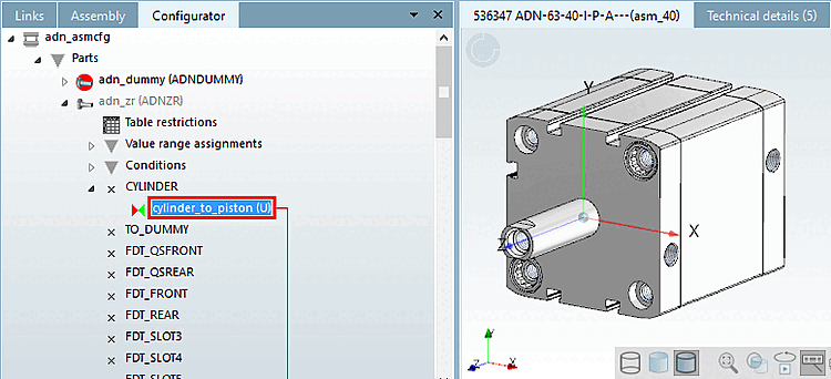
Switch to configuration mode in PARTdataManager and check which rule represents the connection between the moving parts - for example, between the cylinder and piston. Open the rule.
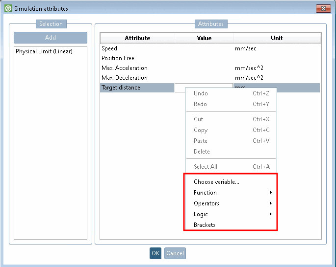
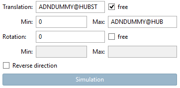
In the Positioning dialog area, the Translation [Translation] " Free [free] " checkbox must be activated and the minimum [Min] and maximum values must be specified according to the physical limits of the "real" product. (In this example, we are dealing with a translation [Translation] movement of the piston rod)
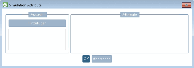
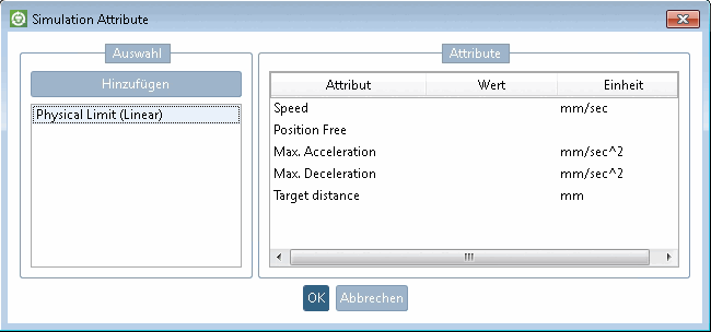
-> The Simulation Attributes [Simulation attributes] dialog box opens.
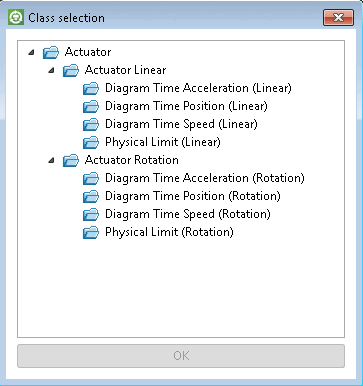
-> The Class selection dialog box opens.
Select Actuator > Actuator Linear > Physical Limit (Linear) and confirm with .
-> The respective attribute is displayed in the dialog box.
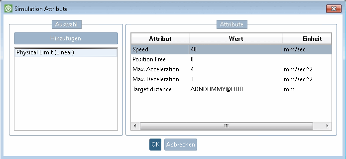
Determine the values of the attributes according to the real product.
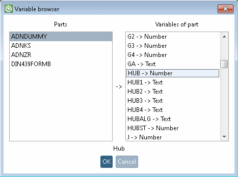
In the context menu of an opened field you can find different helpful functions.
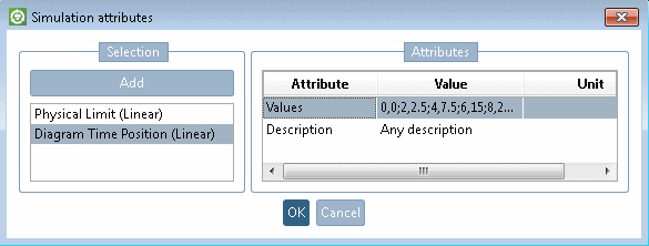
Optionally, additional motion profiles can be set to execute a dynamic motion (for example, given by motion diagrams in the original product data) In this case, click again and then select Actuator > Actuator Linear > Diagram Time Position.
Then determine the values according to the following pattern. (Any number of pairs is possible.)
Zeit,Position;Zeit,Position;etc.
0,0;2,2.5;4,7.5;6,15;8,25;10,40
Several motion profiles can also be added if different diagrams with different loads are available, for example. You can later use these individually in the Mechatronics Concept Designer. To distinguish them from each other, you can add a description in the dialog box.
The component is now ready for export for testing. See below.
![[Note]](https://webapi.partcommunity.com/service/help/latest/pages/en/3dfindit/doc/images/note.png)