3.5.3. Insert from the standard and purchased parts library via "PARTdataManager" 3.5.3.3.
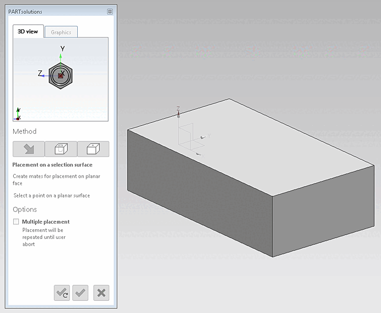
"On surface"
|  |
| Prev | Next |
![[Note]](https://webapi.partcommunity.com/service/help/latest/pages/en/3dfindit/doc/images/note.png)
Use the buttons below to confirm the
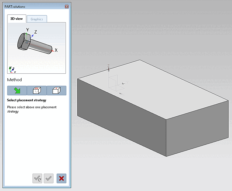
Placements are still inactive. By clicking on  you can change the placement action
abort.
you can change the placement action
abort.
Click the
 to Face [On surface] button.
-> The 3D view in the placement dialog now shows the possible connection points. (If several connection points are possible, corresponding information is displayed in the placement dialog).
-> In the placement dialog on the Graphics Tabbed page, you will find 3D images of the component or technical views(if available).
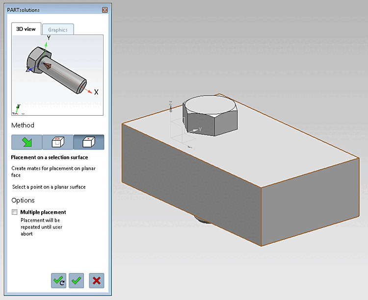
Select a point on an area [Select point on surface].
Click Place once
 or Multiple
Place [Place multiple]
or Multiple
Place [Place multiple]
 .
.
Optionally make further placements or close placement dialog
Place multiple times [Place multiple] (and leave dialog open)
Place once (and close dialog)
Close dialog (without placement)