![[Note]](https://webapi.partcommunity.com/service/help/latest/pages/en/3dfindit/doc/images/note.png) | Note |
|---|---|
| |
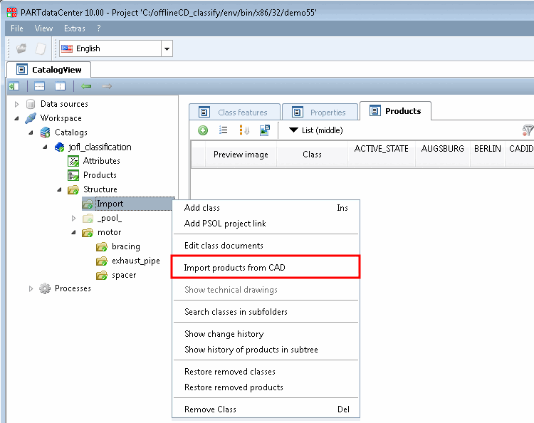
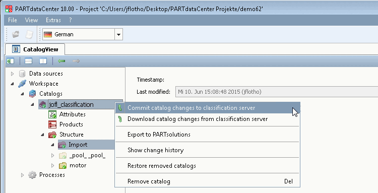
Select the import directory in the structure view [Structure] and click on the Import products from CAD command in the context menu.
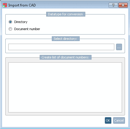
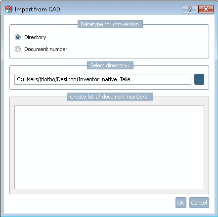
To select a directory, click on the Browse button
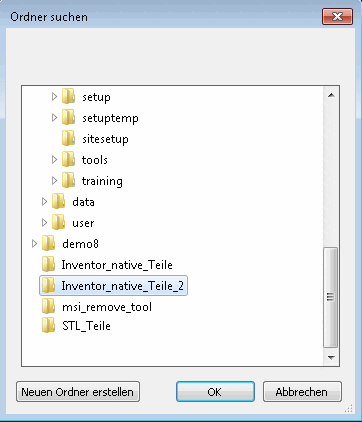
Specify the directory in which the native CAD parts are located and confirm with .
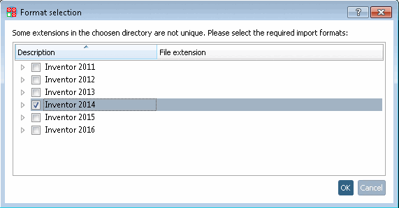
-> The Format selection dialog box appears.
Activate the checkbox for the appropriate CAD system version and confirm with .
-> Directory selection [Select directory]: The path to the desired import directory is now entered.
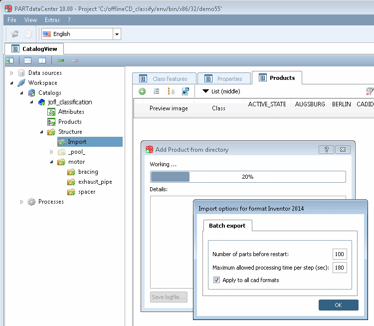
-> The import process is started and the Import options for format <CAD system> dialog box appears. Make any necessary adjustments and confirm with .
Normally the dialog would open for each format, e.g. for .prt and .asm. If the option is activated then the dialog won't be displayed a second time.
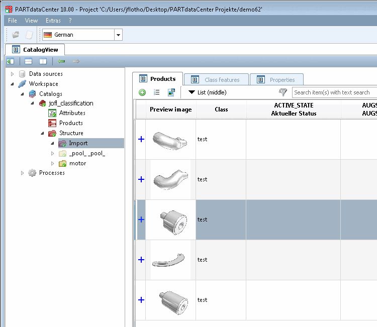
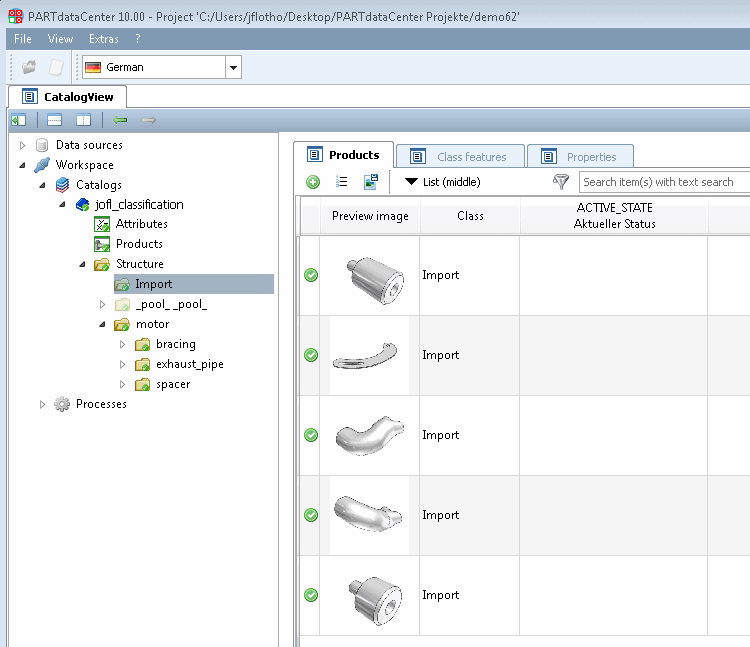
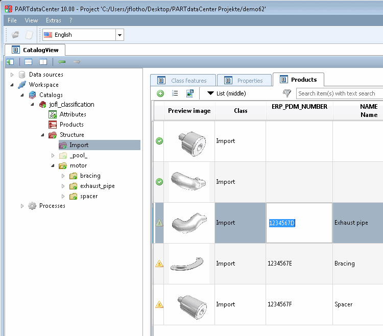
The import process now runs through and the imported components are displayed on the Products tab page. Each line is marked with a blue plus sign, which indicates that the products have not yet been uploaded to the server.
Commit changes to the server, now or later.
-> After an upload the products are marked by a green checkmark.
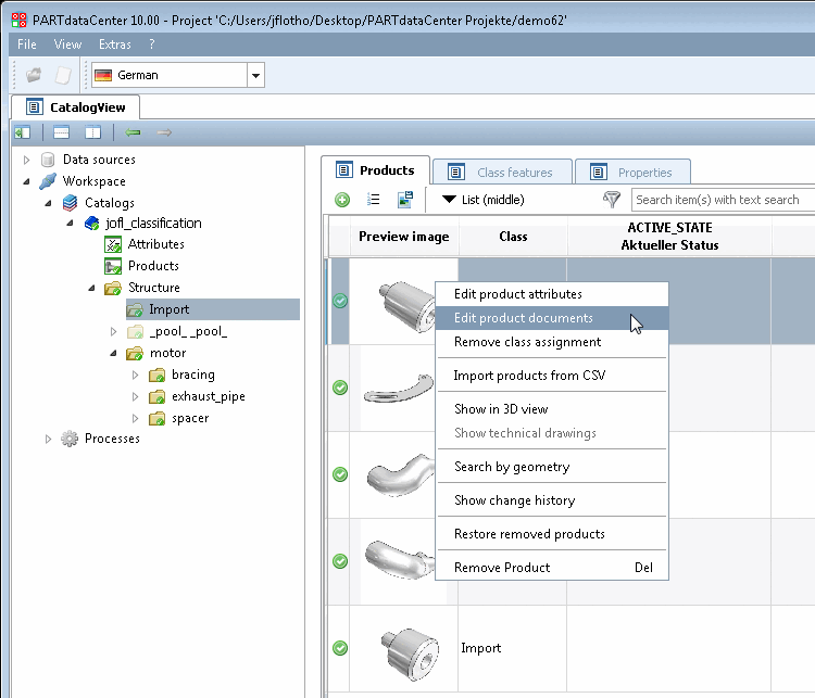
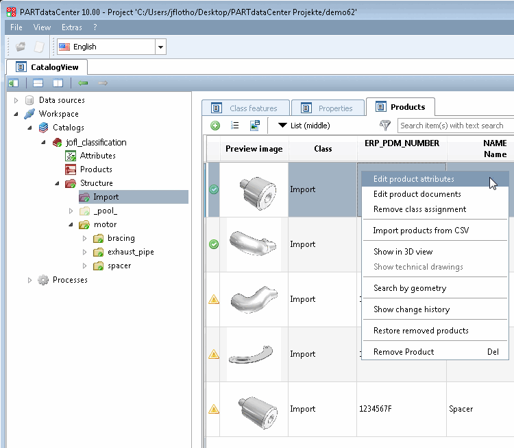
Click on the Edit product documents command in the context menu of a product.
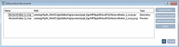
-> The same-named dialog box opens.
The imported product has a geometry in zjv format and a preview image in png format, which were automatically generated from the native CAD file during the import process.
You can use , , and to replace the documents or add new ones (e.g. a technical drawing).
In order to edit product attributes directly click into table fields.
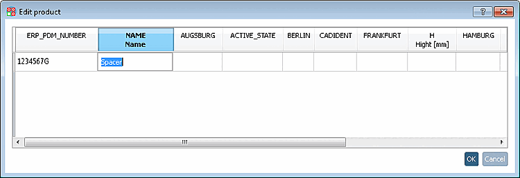
Alternatively, click the context menu command Edit product attributes.
-> The Edit product dialog box opens. Click in the desired field to edit.