7.13.5. Docking window "Configurator " - Specify configuration
7.13.5.2. Context menu "" - Insert part...
|  |
| Prev | Next |
To add parts to a configuration, call up the context menu command Insert part [Add Part] above the Parts element.
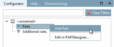
-> An Explorer window is opened.
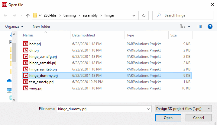
Select a project file [Project file] (*.prj) and confirm by clicking on .
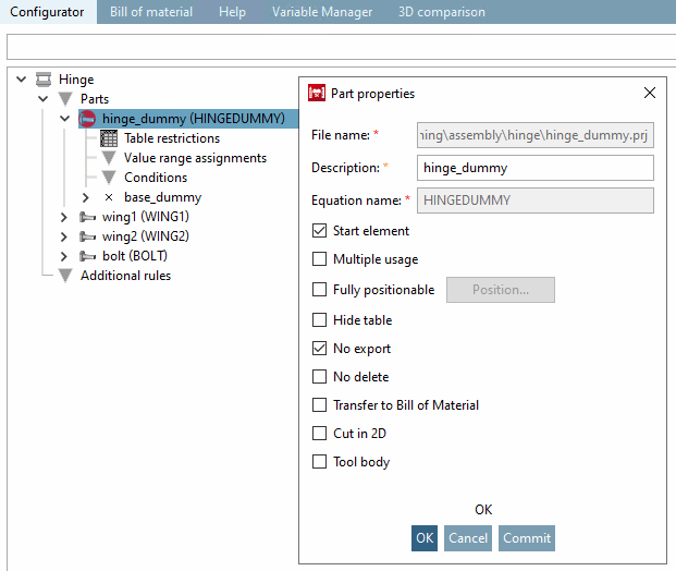
-> The Part properties dialog box opens.
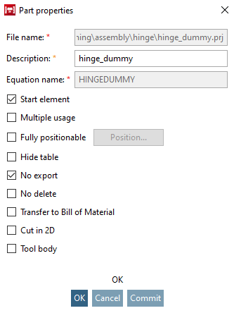
File name: ...is entered automatically. Storage location of the component.
Designation: ...for the component within the configurator directory tree.
Formula name [Equation name] ...for the internal referencing of the component. Appears in brackets after the designation.
Start element: The component from which the creation of a set of rules is to begin is defined as the start element [Start element]. Check the corresponding option. Start elements are marked in the directory tree with a red circle
 in the directory tree.
Reusable [Multiple usage] a component can be inserted into the assembly in different positions and with different dimensions.
Absolutely position [Fully positionable] able:
This option enables shifting by a specified vector to any position in space.
As soon as you activate the option, the .. button becomes active.
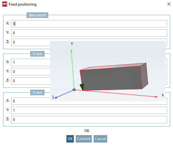
After clicking on .. the Absolute positioning [Fixed positioning] dialog box opens.
The dialog is divided into 3 sections.
In the example above, the component was moved 5 units to the right in the direction of the X-axis and pivoted upwards in the X-Y plane (Z=0) using vector (1; 0.1). No changes were made to the orientation of the Y-axis of the component.
Hide table the corresponding table is thus not visible in PARTdataManager.
Do not export [No export] when exporting the assembly from PARTdataManager to a CAD system, this component is not included.
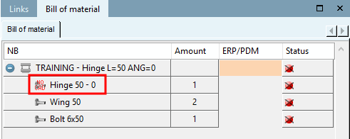
Parts with the Do not export [No export] option are displayed in the PARTdataManager, in the dialog area Structure [Assembly], parts list [Bill of material] the icon NO CAD
 dialog area (see following illustration).
[109]
dialog area (see following illustration).
[109]
Not er [No delete] asablecomponent cannot be removed from stencil.
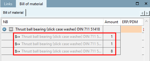
Transfer to parts list [Transfer to Bill of Material]: The relevant part is transferred to the PARTbom order list.
Parts without the option Transfer to parts list [Transfer to Bill of Material] appear grayed out in the PARTdataManager "NO BOM" appears grayed out in the dialog area Structure [Assembly], parts list [Bill of material] (see following figure). [110]
Cut in 2D: ... defines whether the part should also be affected when cutting in 2D. Remove the check mark, for example, for screws that you do not want to have hatched when cutting.
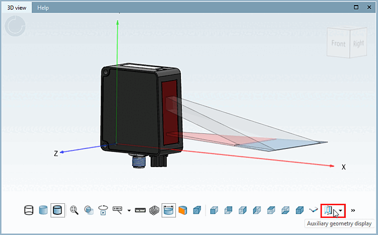
Tool body: If you define a component as a tool body, it is shown or hidden when you press Auxiliary geometry display.
![[Note]](https://webapi.partcommunity.com/service/help/latest/pages/en/installation/doc/images/note.png)