2.1.7.1. Determine characteristic in "Table" view
2.1.7.1.4. Columns with
value range fields
|  |
| Prev | Next |
Some parts have Value range variables in addition. For these no fixed value is specified.
At these parts, in order to completely specify the characteristic, the value ranges have to be specified in addition.
Columns with value range fields are marked with colored icons ( |
|  |
|  ). In addition, depending on the settings, the columns are also colored. See below for the meaning of the different colors.[77]
The selected row
shows the respective icon as well. In order to enter a certain value, click
on the icon .
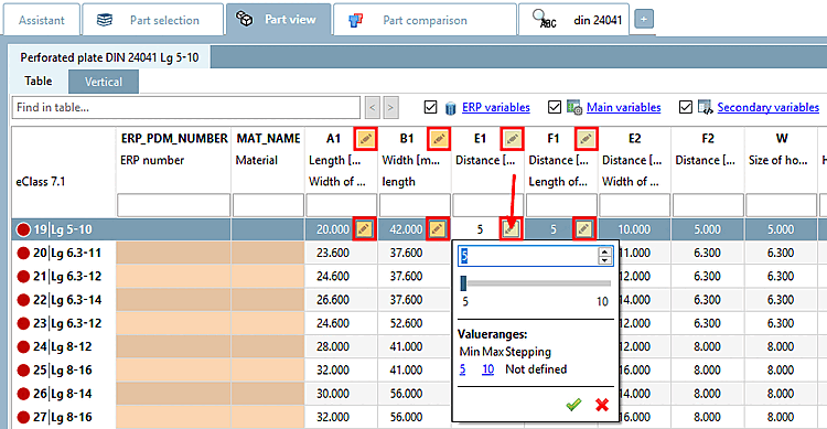
The dialog may look different depending on the component specifications.
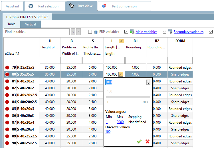
Value range: Simply enter a desired value within the value range in the open input field or select the value using the slider (if active). Then confirm by clicking on the green tick.
The red line depicts the default value. By clicking on it, the default can be restored anytime.
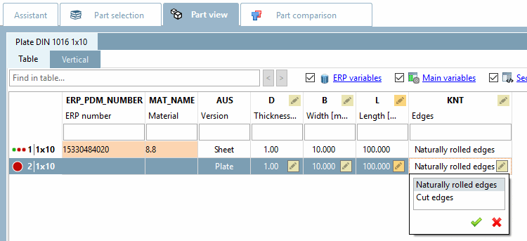
Selection of discrete values: Select the desired option in the list field and confirm by clicking on the green tick.
Selection of discrete values with preview images:
In some value range fields graphics can be used for exemplification.
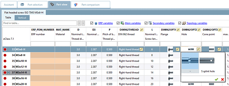
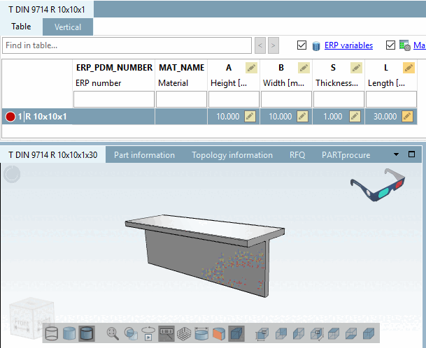
Changing the table entry immediately changes the display in the 3D view.
Meaning of colors for value range fields
There are different types of value range fields, which behave differently depending on the existence of an ERP number and are marked by multicolored icons.
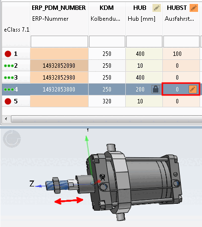
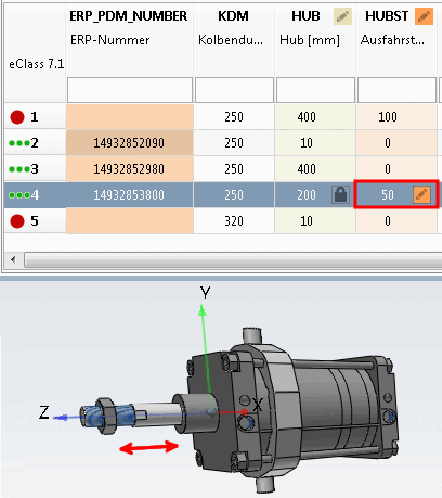
The functional characteristic [Function attribute] is used for stroke and angular positions, for everything that defines a mechanical movement in a part/assembly (e.g. the stroke position of a cylinder).
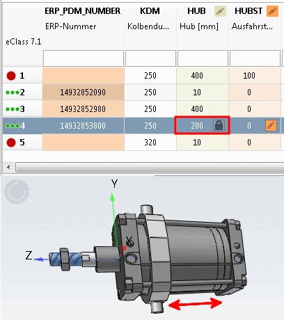
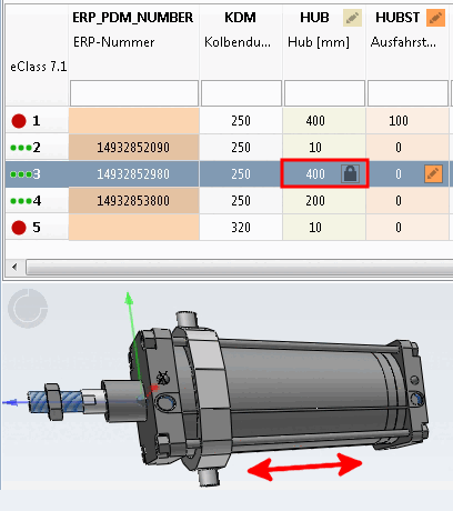
The geometry characteristic [Geometry attribute] is used for characteristics that have an influence on the geometry, e.g. if the geometry of the part or assembly changes due to the variable (e.g. max. stroke length), or if components are added or removed, e.g. "Sensor yes/no" or "Option on/off".
![[Note]](https://webapi.partcommunity.com/service/help/latest/pages/en/installation/doc/images/note.png)
Note In the case of a cylinder, for example, a distinction must be made between the HUB, which is a geometric feature [Geometry attribute], and the stroke position, which is a functional feature [Function attribute]. With ERP functionality, the HUB is pinned as soon as an ERP_PDM_NUMBER has been assigned; the stroke position is not pinned. The pinned status is visible on a special icon
 . Different strokes are also assigned different ERP numbers with ERP functionality; different stroke positions are not.
The dimensional characteristic [Dimension attribute] is used for semi-finished products and profiles that are produced in running meters (here variable L).
Note Whether a dimensional characteristic [Dimension attribute] is pinned when an ERP number is assigned
is set in the configuration file depending on the desired internal company workflow.[a]
If you need another value, use the "neutral" row (without ERP number) beside the pinned one. (Whether rows without ERP number may be exported depends on the desired company internal workflow.)
[a] See Section 5.18.2, “ Pin dimension feature on/off / plinkcommon.cfg -> Block [PARTdataManager] -> Key "LockDimRange" ” in ENTERPRISE 3Dfindit (Professional) - Administration.
The characteristic attribute [Object attribute] is used for values that are required for dimensional and/or product standards, for order numbers or technical specifications, etc. (characteristics that have nothing to do with geometry or function).
Note A characteristic [Object attribute] is pinned as soon as an ERP number has been assigned for the relevant line. It is marked with a corresponding icon
icon.If you need another value, use the "neutral" row (without ERP number) beside the pinned one. (Whether rows without ERP number may be exported depends on the desired company internal workflow.)