2.1.16.6.2.
Part view context menu commands
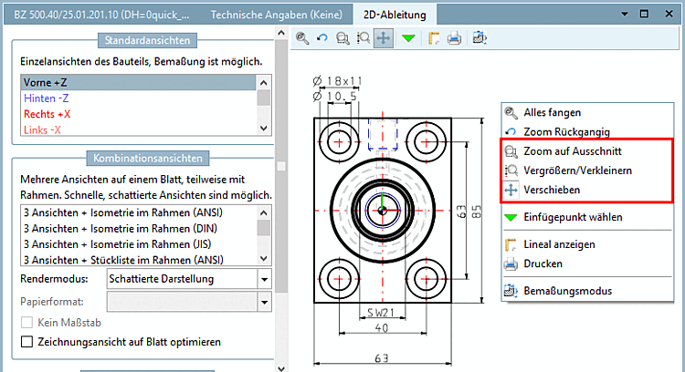
2.1.16.6.2.3. Context menu commands in the "2D derivation " docking window |  |
| Prev | Next |
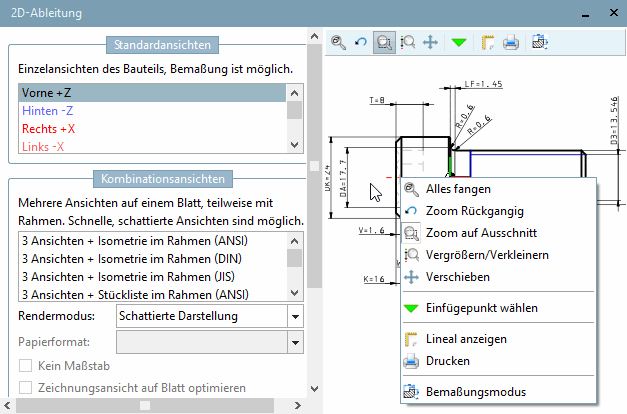
With Snap all [Zoom all], you can bring the display of the component to a balanced size. The component is visible large enough, but does not protrude beyond the 3D view window when rotated. If the Exact zoom [Explicit zoom] option is set (see Section 1.3.5.4.1, “ Operation ” in ENTERPRISE 3Dfindit (Professional) - Administration ), the display within the window is enlarged to the maximum.
Zoom to section [Zoom on window] | Zoom in/out | Move [Pan]
![[Note]](https://webapi.partcommunity.com/service/help/latest/pages/en/partsolutions_user/doc/images/note.png)
Note The basic mouse button assignment is made under PARTdataManager - > Extras -> Settings... -> 3D settings -> Mouse and keyboard. Detailed information on this can be found under Section 1.3.5.4.2, “Mouse and keyboard assignments ” in ENTERPRISE 3Dfindit (Professional) - Administration.
Via context menu command, you can change the assignment of left mouse key.
Turn on the option by clicking on the menu item.
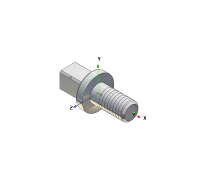
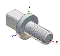
As soon as you move your cursor over a possible insertion point, a catch shows up. Confirm the selection by clicking once.
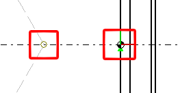
-> The insertion point is displayed with a green arrow.
Turn off the option by selecting another menu item.
Information on the topic insertion point [Insertion point] can also be found under Chapter 7, PARTdesigner in eCATALOG 3Dfindit and Section 7.13.5.7, “Context menu of connection points ” in eCATALOG 3Dfindit.
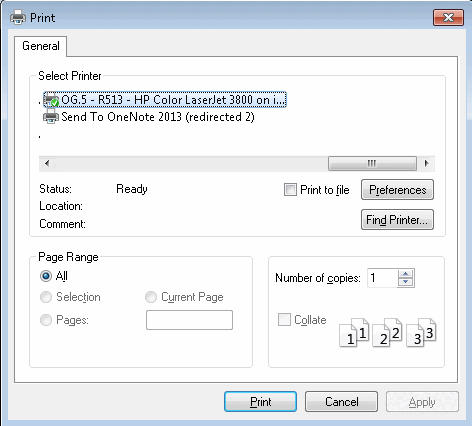
You have the option of creating a printout of the 3D view of the component/assembly.
When clicking on the command the respective settings dialog box of your operation system opens.
!["Dimensioning [Dimensioning] " toolbar](https://webapi.partcommunity.com/service/help/latest/pages/en/partsolutions_user/doc/resources/img/img_fcbb05cfbf9144c7acd9b64166e6744e.png)
| Note |
|---|---|
The individual parameters of dimensions are displayed in the Edit element docking window.
Details on the single tools and their parameters can be found in the following. | |
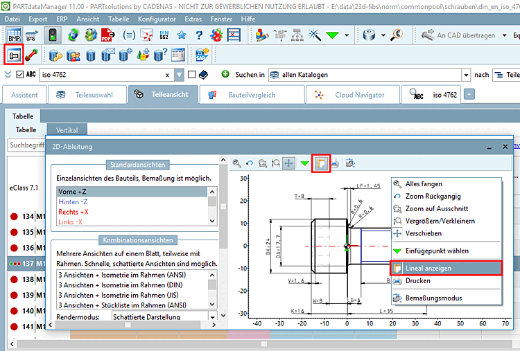
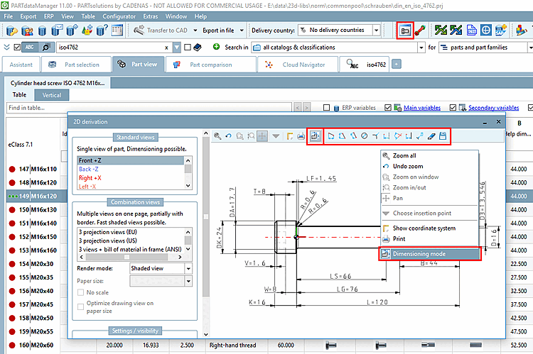
The dimensioning mode can be accessed in various ways:
Via PARTdataManager -> 2D derivation button -> 2D derivation docking window -> Dimensioning mode context menu command or alternatively via Dimensioning mode icon
 .
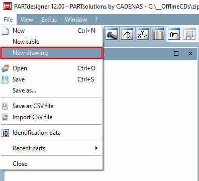
.Via PARTdesigner -> Docking window 3D History -> Context menu Plane -> New 2D drawing [New 2D drawing...]..
-> A view with Sketch History [Sketch history] and Sketcher opens.
Via PARTdesigner -> File menu [File] -> New drawing
![Call New 2D drawing. [New 2D drawing...].](https://webapi.partcommunity.com/service/help/latest/pages/en/partsolutions_user/doc/resources/img/img_d307115ee0e2480cb7a96a95db2dd091.png)
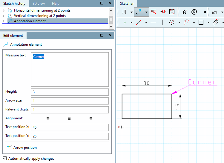
The individual tools/functions in dimensioning mode [Dimensioning mode] are explained below:
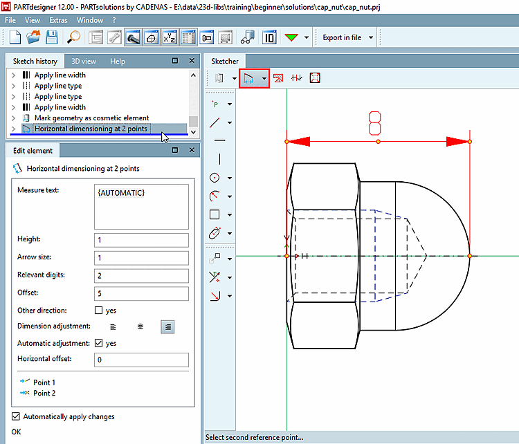
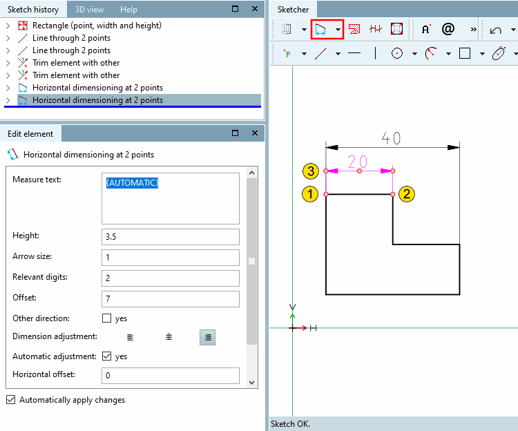
 Horizontal dimensioning at 2 points
Select dimension position or base dimension [Select dimension position or base dimension...]...: Drag the dimension line to the desired position.
If it is about multiple dimensionings which shall connected with always the same offset, then first click on a base dimension and then on the desired position. In this case the offset refers to the base dimension and not on the line to be dimensioned itself. When a base dimension changes, all dimensioning based on it are also automatically changed.
-> The Edit element docking window opens.
If necessary, adjust the values of the individual parameters in the Edit element docking window:
By default, "{AUTOMATIC}" is displayed in curly braces.
"AUTOMATIC" takes the current value from the geometry.
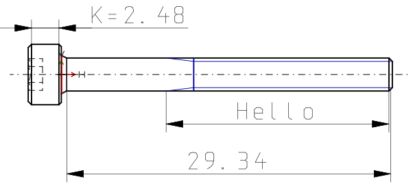
Form the dimension text [Dimension text] statically or dynamically or mixed static-dynamic.
Hello
Dimension text: static-dynamic
K={K}Enter only the desired variable. The respective value is generated dynamically.
{L}Relevant digits: Here you can define the decimal places [Decimal digits] of dimension text [Dimension text].
Other direction: The dimension line is positioned on the other side of the object.
Dimensional alignment [Dimension adjustment]:
Horizontal offset: Determines the horizontal offset of the dimension text from the center point.
 Vertical dimensioning at 2 points
See horizontal dimension at 2 points [Horizontal dimensioning at 2 points]
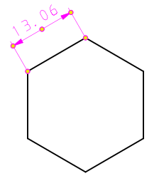
 Parallel dimensioning at 2 points
See horizontal dimension at 2 points [Horizontal dimensioning at 2 points]
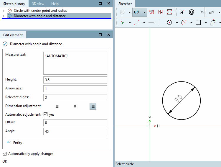
 Diameter with angle and distance
Select circle: Click on the circle to be dimensioned. --> The dimension line appears.
Select dimension position: Position the dimension (inside or outside the circle).
Option 1: Fix the angle [Angle] of the line with a single mouse click. Then drag the entire dimensioning to the desired position [Position] and fix it with a mouse click.
Option 2: Fix the angle and position of the dimensioning in one step by double-clicking with the mouse.
If necessary, adjust the dimensioning in the Edit element docking window using the input fields.
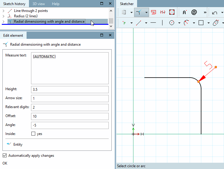
 Radial dimensioning with angle and distance
Create radius of a circle or arc
Select dimension position: Position the dimensioning and fix it with a mouse click.
If necessary, adjust the individual parameters of the dimensioning in the Edit element docking window using the input fields.
For example, you can adjust the angle. 0° lays on the bisecting line of the segment of the circle.
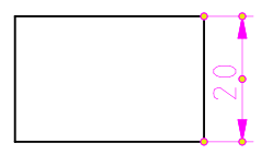
 Half value offset dimension from line
Select reference line [Select reference line...]...: Click on the reference line (rotation axis).
Select dimension point [Select dimension point...]...: Click on the point whose distance to the reference line is to be dimensioned.
Select dimension position or base dimension [Select dimension position or base dimension...]...: Click on a point in free space that approximately reflects the desired offset to the point.
If it is about multiple dimensionings with always the same offset, first click on a base dimension and only then on a point in the free space. In this case, the offset refers to the base dimension and not to the point.
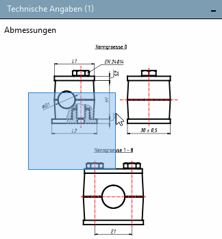
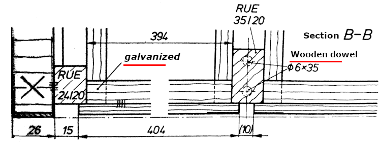
The drawing illustrates the dimension between rotational axis and line to be dimensioned (on the right [standard vertical dimensioning]) and half dimensioning (on the left [duplicate value]).
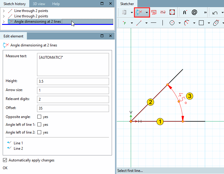
Select second line... [Choose second line...] (counterclockwise)
Select the distance and position of the dimension [Select distance and orientation of dimension...]...: The angle will be spanned depending on the selected quadrant.
If necessary, adjust the parameters in the Edit element docking window.
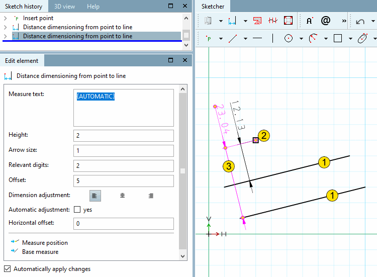
 Distance dimensioning from point to line
Select reference line [Select reference line...]...: Click on the reference line.
Select dimension point [Select dimension point...]...: Click on the point whose distance to the reference line is to be dimensioned.
Select dimension position or base dimension [Select dimension position or base dimension...]...: Click on a point in free space that approximately reflects the desired offset to the point.
If it is about multiple dimensionings with always the same offset, first click on a base dimension and only then on a point in the free space. In this case, the offset refers to the base dimension and not to the point.
These markup elements are partial notations and can be used in a variety of ways.
Follow the instructions of the status line:
![Dimension orientation [Dimension adjustment]: left](https://webapi.partcommunity.com/service/help/latest/pages/en/partsolutions_user/doc/resources/img/img_5e8cd0ae432144c2bf1e01baa653ac65.png)
![Dimension alignment [Dimension adjustment]: centered](https://webapi.partcommunity.com/service/help/latest/pages/en/partsolutions_user/doc/resources/img/img_f6eaa02f8c5e4f68b113161980c26309.png)
![Dimension orientation [Dimension adjustment]: right](https://webapi.partcommunity.com/service/help/latest/pages/en/partsolutions_user/doc/resources/img/img_6c7b6398bbc342c0b12d3192eb751af2.png)
![The drawing illustrates the dimension between rotational axis and line to be dimensioned (on the right [standard vertical dimensioning]) and half dimensioning (on the left [duplicate value]).](https://webapi.partcommunity.com/service/help/latest/pages/en/partsolutions_user/doc/resources/img/img_0cfcea26618e46378cb1f32141e2b0eb.png)


In the PARTdataManager the following two tools are available in the dimensioning toolbar, in the PARTdesigner in the standard toolbar.


When moving the cursor over a dimensioning it will show up in red.
Context menu: Clicking with the secondary mouse button displays the context menu.
In the PARTdataManager you can make the following changes:
Change parameters [Change parameters...]...: The Change [Change parameter] parameters dialog box is called up.
Delete [Delete step] step: The selected dimensioning is deleted.
Delete step including dependent [Delete step include dependent elements]: The selected dimensioning is deleted including dependent.