
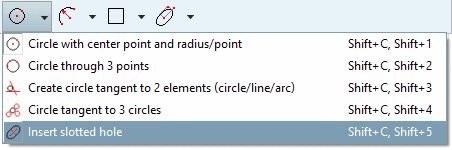
- 1.3.1.2.2.18.1. Insert slotted hole
- 1.3.1.2.2.18.2. Sketcher: Variable positioning with "Horizontal by point" or "Vertical by point"
- 1.3.1.2.2.18.3. Feature with connections to multiple 3D history elements allowed
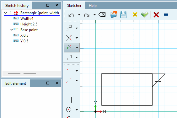
- 1.3.1.2.2.18.4. Sketcher: New function "Bevel centered on 2 lines over 2 feed lengths"
- 1.3.1.2.2.18.5. Chamfer on the outside
- 1.3.1.2.2.18.6. Sketcher: "Insert hexagon" function simplified
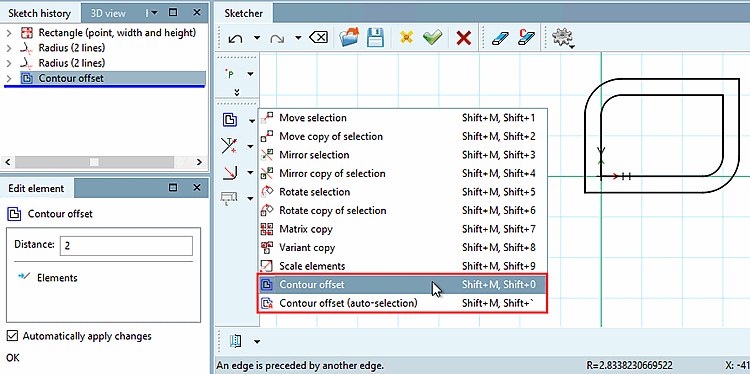
- 1.3.1.2.2.18.7. Sketcher: Contour offset supported in sketches
The function
 Insert slotted hole
was only available for testing purposes for versions < 12.12 and is
now officially released and available with version 12.12.
Insert slotted hole
was only available for testing purposes for versions < 12.12 and is
now officially released and available with version 12.12.
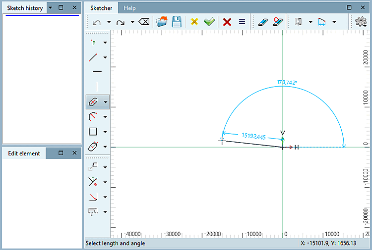
The following example shows the determination of the slot with 3 free clicks. However, it is also possible to create fixed reference points beforehand. These can be, for example, the end point of a line or the center of a circle. Depending on the procedure, different input fields are displayed in the Edit element docking window.
Determine the position of the first semicircle by clicking freely.
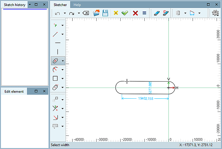
Determine the distance of the second semicircle to the first and the angle to the first point by clicking freely.
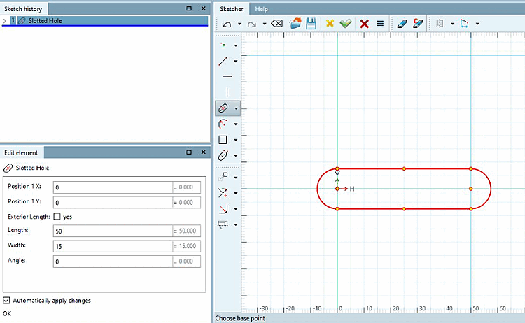
Adjust the individual parameters in the Edit element docking window.
Optionally, you can specify the definition of the outer length [Exterior Length]:

Further details (on creating with the use of reference points) can be found under Section 7.9.3.7.7, “ Insert slotted hole ” in eCATALOG 3Dfindit.
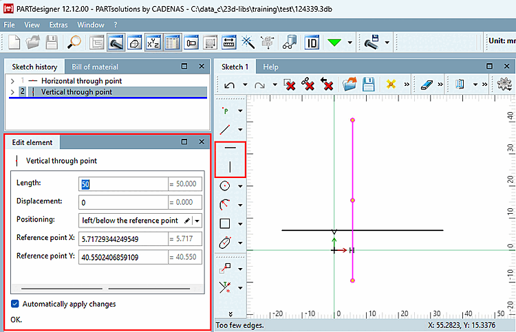
The option Horizontal through point / Vertical through point with different positioning to the origin is now officially released with V12.12 (was only available internally as a breaking feature from V12.7).
![[Note]](https://webapi.partcommunity.com/service/help/latest/pages/en/partsolutions_user/doc/images/note.png)
The following illustration shows a body on which a circumferential cut-out has been made in the upper half.
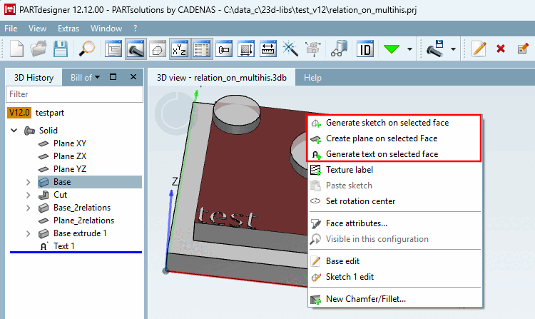
This means that the upper surface has dependencies on several 3D history [3D History] elements.
![The marked sketch has dependencies to several 3D history [3D History] elements.](https://webapi.partcommunity.com/service/help/latest/pages/en/partsolutions_user/doc/resources/img/img_96ca90f89d4344ba8feac270397bd718.png)
Under these circumstances, it was not permitted in versions 12.6 to 12.11 to use the Create new sketch on selected area [Generate sketch on selected face], Create new layer on selected area [Create plane on selected Face] and Create new text on selected area [Generate text on selected face] features. These features were only available for test purposes. The corresponding context menu commands were deactivated by default. With V12.12, the use of these features is now also permitted and officially released for sketch relationships to several 3D history [3D History] elements.
In Sketcher there is the new function Chamfer centered on 2 lines over 2 feed lengths [Chamfer centered at 2 lines with 2 distances].[2]
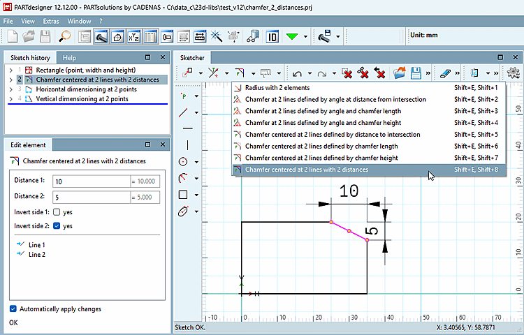
To create the chamfer, call up the context menu command Center chamfer on 2 lines over 2 indent lengths [Chamfer centered at 2 lines with 2 distances] and follow the instructions in the status bar.
See also Section 7.9.3.13, “ Modify -> Crop (part 2)” in eCATALOG 3Dfindit 2 Section 7.9.3.13, “ Modify -> Crop (part 2)” in eCATALOG 3Dfindit
The function
Rounding to 2 elements [Radius with 2 elements]
 was not official with V12.8 as a breaking feature
and is now officially available with V12.12.
was not official with V12.8 as a breaking feature
and is now officially available with V12.12.
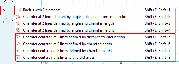
With the following features, it is now possible to place the chamfer outside the outlined body:
Bevel centered on 2 lines over distance to intersection [Chamfer centered at 2 lines defined by distance to intersection]
Bevel centered on 2 lines over bevel length [Chamfer centered at 2 lines defined by chamfer length]
Bevel centered on 2 lines over feed length [Chamfer centered at 2 lines defined by chamfer height]
Bevel centered on 2 lines over 2 feed lengths [Chamfer centered at 2 lines with 2 distances]
Details on this can be found under Section 7.9.3.13, “ Modify -> Crop (part 2)” in eCATALOG 3Dfindit.
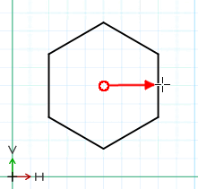
The Insert hexagon function has been simplified. You can determine the approximate rotation directly when dragging and then adjust it directly in the Edit element docking window.[3]
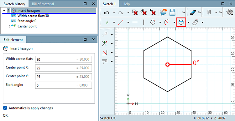
See also Section 7.9.3.6, “ Forms -> Special ” in eCATALOG 3Dfindit.
This feature Konturoffset [Contour offset] was only an unofficial test version for versions < 12.12. For versions >= 12.12 the feature is now officially available.
The contour offset [Contour offset] tool creates a duplicate of the contour with a scaling factor. Simply enter the desired distance [Distance] to the original contour in the Edit element docking window. (Feature for demo purposes only, not released.)
See also Section 7.9.3.11, “ Modify -> Transform ” in eCATALOG 3Dfindit.
[2] The function has been available as a breaking feature since v12.6 and was therefore not allowed to be used productively. Now with v12.12 it is officially released and available.
[3] The function was only available from v12.5 to v12.11 for test purposes and not for productive use; it is now officially released and available with v12.12.